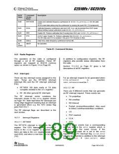
C2510Fx / CC2511Fx
RFST
Value
Command
Strobe
Description
Name
0x00
0x01
SFSTXON
Enable and calibrate frequency synthesizer (if MCSM0.FS_AUTOCAL=1). If in RX (with
CCA):
Go to a wait state where only the synthesizer is running (for quick RX / TX turnaround).
SCAL
Calibrate frequency synthesizer and turn it off. SCALcan be strobed from IDLE mode
without setting manual calibration mode (MCSM0.FS_AUTOCAL=0)
0x02
0x03
SRX
STX
Enable RX. Perform calibration first if coming from IDLE and MCSM0.FS_AUTOCAL=1.
In IDLE state: Enable TX. Perform calibration first if MCSM0.FS_AUTOCAL=1.
If in RX state and CCA is enabled: Only go to TX if channel is clear.
0x04
SIDLE
SNOP
Enter IDLE state (frequency synthesizer turned off).
No operation.
All
others
Table 61: Command Strobes
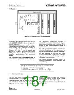
14.2 Radio Registers
The operation of the radio is configured
through a set of RF registers. These RF
registers are mapped to XDATA memory
space as shown in Figure 14 on Page 40 .
In addition to configuration registers, the RF
registers also provide status information from
the radio.
Section 11.2.3.4 on Page 47 gives a full
description of all RF registers.
14.3 Interrupts
There are two interrupt vector assigned to the
radio. These are the RFTXRX interrupt
(interrupt #0) and the RF interrupt (interrupt
#16):
For an interrupt request to be generated when
TCON.RFTXRXIF
is
asserted,
IEN0.RFTXRXIEmust be 1.
• RFTXRX: RX data ready or TX data
complete (related to the RFDregister)
14.3.1.2 RF
There are 8 different events that can generate
an RF interrupt request. These events are:
• RF: All other general RF interrupts
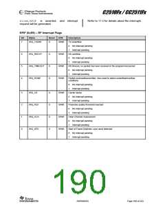
The RF interrupt vector combines the
interrupts shown in the RFIM register shown
on Page 191. Note that these RF interrupts are
rising-edge triggered meaning that an interrupt
is generated when e.g. the SFD status flag
goes from 0 to 1.
• TX underflow
• RX overflow
• RX timeout
• Packet received/transmitted. Also used
to detect overflow/underflow conditions
The RF interrupt flags are described in the
next section.
• CS
• PQT reached
• CCA
14.3.1 Interrupt Registers
14.3.1.1 RFTXRX
• SFD
Each of these events has a corresponding
interrupt flag in the RFIF register which is
asserted when the event occurs. If the
corresponding mask bit is set in the RFIM
register, the CPU interrupt flag S1CON.RFIF
will also be asserted in addition to the interrupt
flag in RFIF. If IEN2.RFIE=1 when
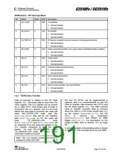
The RFTXTX interrupt is related to the RFD
register. The CPU interrupt flag RFTXRXIF
found in the TCON register is asserted when
there are data in the RFD register ready to be
read (RX), and when a new byte can be written
(TX).
SWRS055D
Page 189 of 243

 TAOS [ TEXAS ADVANCED OPTOELECTRONIC SOLUTIONS ]