C2510Fx / CC2511Fx
The preamble pattern is an alternating
sequence of ones and zeros (101010101…).
The minimum length of the preamble is
programmable through the NUM_PREAMBLE
field in the MDMCFG1 register. When enabling
TX, the modulator will start transmitting the
preamble. When the programmed number of
preamble bytes have been transmitted, the
modulator will send the sync word, and then
data from the RFDregister. If no data has been
written to the RFD register when the radio is
done transmitting the programmed number of
preamble bytes, the modulator will continue to
send preamble bytes until the first byte is
written to RFD.It will then send the sync word
followed by the data written to RFD.
the destination address byte in the packet with
the programmed node address in the ADDR
register and the 0x00 broadcast address when
PKTCTRL1.ADR_CHK=10 or both 0x00 and
0xFF
broadcast
addresses
when
PKTCTRL1.ADR_CHK=11. If the received
address matches a valid address, the packet
is accepted and the RFTXRXIFflag is asserted
and a DMA trigger is generated. If the address
match fails, the packet is discarded and
receive mode restarted (regardless of the
MCSM1.RXOFF_MODE
setting).
The
RFIF.IRQ_DONE flag will be asserted but the
DMA will not be triggered.
14.8.3.2 Maximum Length Filtering
The synchronization word is a two-byte value
set in the SYNC1 and SYNC0 registers. The
sync word provides byte synchronization of the
incoming packet. A one-byte sync word can be
emulated by setting the SYNC1 value to the
preamble pattern. It is also possible to emulate
In
variable
packet
length
mode,
the
PKTCTRL0.LENGTH_CONFIG=1,
PKTLEN.PACKET_LENGTH register value is
used to set the maximum allowed packet
length. If the received length byte has a larger
value than this, the packet is discarded and
receive mode restarted (regardless of the
MCSM1.RXOFF_MODE
RFIF.IRQ_DONE flag will be asserted but the
a
32
bit
sync
word
by
using
MDMCFG2.SYNC_MODEset to 3 or 7. The sync
word will then be repeated twice.
setting).
The
CC2510Fx/CC2511Fx supports both fixed packet
length protocols and variable packet length
protocols. Variable or fixed packet length
mode can be used for packets up to 255
bytes.
DMA will not be triggered.
14.8.4
Packet Handling in Transmit Mode
The payload that is to be transmitted must be
written into RFD. The first byte written must be
the length byte when variable packet length is
enabled. The length byte has a value equal to
the payload of the packet (including the
optional address byte). If fixed packet length is
enabled, then the first byte written to RFD is
interpreted as the destination address, if this
feature is enabled in the device that receives
the packet.
Fixed packet length mode is selected by
setting PKTCTRL0.LENGTH_CONFIG=0. The
desired packet length is set by the PKTLEN
register.
In
variable
packet
length
mode,
PKTCTRL0.LENGTH_CONFIG=1, the packet
length is configured by the first byte after the
sync word. The packet length is defined as the
payload data, excluding the length byte and
the optional CRC. The PKTLEN register is
used to set the maximum packet length
allowed in RX. Any packet received with a
length byte with a value greater than PKTLEN
will be discarded.
The modulator will first send the programmed
number of preamble bytes. If data has been
written to RFD, the modulator will send the two-
byte (optionally 4-byte) sync word and then the
content of the RFD register. If CRC is enabled,
the checksum is calculated over all the data
pulled from the RFD register and the result is
sent as two extra bytes following the payload
data. If fewer bytes are written to the RFD
registers than what the radio expects the radio
will enter TX_UNDERFLOW state and the
RFIF.IRQ_TXUNF flag will be set together
with RFIF.IRQ_DONE. An SIDLE strobe
needs to be issued to return to IDLE state.
14.8.3
Packet Filtering in Receive Mode
CC2500 supports two different types of packet-
filtering: address filtering and maximum length
filtering.
14.8.3.1 Address Filtering
Setting PKTCTRL1.ADR_CHK to any other
value than zero enables the packet address
filter. The packet handler engine will compare
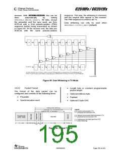
If whitening is enabled, everything following
the sync words will be whitened. This is done
before the optional FEC/Interleaver stage.
SWRS055D
Page 196 of 243

 TAOS [ TEXAS ADVANCED OPTOELECTRONIC SOLUTIONS ]