C2510Fx / CC2511Fx
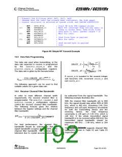
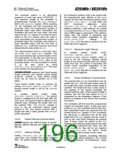
; Transmit the following data: 0x02, 0x12, 0x34
; (Assume that the radio has already been configured, the high speed
; crystal oscillator is selected as system clock, and CLKCON.CLKSPD=000)
MOV
JNB
CLR
MOV
JNB
CLR
MOV
JNB
CLR
MOV
RFST,#03H
RFTXRXIE,C1
RFTXRXIE
RFD,#02H
RFTXRXIE,C2
RFTXRXIE
RFD,#12H
RFTXRXIE,C3
RFTXRXIE
; Start TX with STX command strobe
; Wait for interrupt flag telling radio is
; ready to accept data, then write first
; data byte to radio (packet length = 2)
; Wait for radio
;
; Send first byte in payload
; Wait for radio
C1:
C2:
C3:
;
RFD,#34H
; Send second byte in payload
; Done
Figure 48: Simple RF Transmit Example
14.5 Data Rate Programming
The data rate used when transmitting, or the
data rate expected in receive is programmed
RDATA ⋅220
⎢
⎥
⎥
⎛
⎜
⎜
⎝
⎞
⎟
⎟
⎠
DRATE _ E = log
⎢
2
fref
⎢
⎣
⎥
⎦
by
the
MDMCFG3.DRATE_M
and
the
RDATA ⋅228
MDMCFG4.DRATE_E configuration registers.
The data rate is given by the formula below.
DRATE _ M =
− 256
fref ⋅ 2DRATE _ E
If DRATE_M is rounded to the nearest integer
and becomes 256, increment DRATE_E and
use DRATE_M=0.
(
256 + DRATE _ M
⋅2DRATE _ E
)
RDATA
=
⋅ fref
228
The following approach can be used to find
suitable values for a given data rate:
14.6 Receiver Channel Filter Bandwidth
In order to meet different channel width
requirements, the receiver channel filter is
programmable. The MDMCFG4.CHANBW_E and
MDMCFG4.CHANBW_M configuration registers
control the receiver channel filter bandwidth.
The following formula gives the relation
between the register settings and the channel
filter bandwidth:
be subtracted from the signal bandwidth. The
following example illustrates this:
With the channel filter bandwidth set to 600
kHz, the signal should stay within 80% of 600
kHz, which is 480 kHz. Assuming 2.44 GHz
frequency and ±20 ppm frequency uncertainty
for both the transmitting device and the
receiving
device,
the
total
frequency
uncertainty is ±40 ppm of 2.44 GHz, which is
±98 kHz. If the whole transmitted signal
bandwidth is to be received within 480 kHz, the
transmitted signal bandwidth should be
maximum 480 kHz – 2·98 kHz, which is 284
kHz.
fref
BWchannel
=
8⋅(4 + CHANBW_ M )·2CHANBW_ E
For best performance, the channel filter
bandwidth should be selected so that the
signal bandwidth occupies at most 80% of the
channel filter bandwidth. The channel centre
tolerance due to crystal accuracy should also
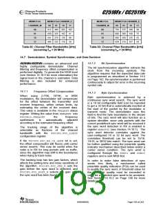
The CC2510Fx/CC2511Fx supports channel filter
bandwidths shown in Table 62 and Table 63
respectively.
SWRS055D
Page 192 of 243

 TAOS [ TEXAS ADVANCED OPTOELECTRONIC SOLUTIONS ]