9 - 60 V
0 - 60 V
5 A
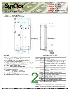
Input:
Outputs:
Current:
Package:
Eighth-brick
Technical Specification
100
95
90
85
80
75
70
65
60
6
5
4
3
2
1
0
48Vin 24Vout
24Vin 12Vout
48Vin 12Vout
24Vin 48Vout
12Vin 24Vout
12Vin 48Vout
48Vin 24Vout
24Vin 12Vout
48Vin 12Vout
24Vin 48Vout
12Vin 24Vout
12Vin 48Vout
0
1
2
3
4
5
0
1
2
3
4
5
Load Current (A)
Load Current (A)
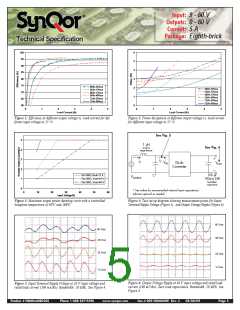
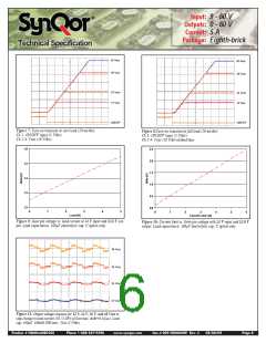
Figure 1: Efficiency at different output voltage vs. load current for dif-
Figure 2: Power dissipation at different output voltage vs. load current
ferent input voltage at 25 °C
.
for different input voltage at 25 °C.
See Fig. 5
5
4
3
2
1
0
1ꢀµH
See Fig. 6
source
impedance
iC
iS
VIN
Dc-dc
Converter
VOUT
Tb≤100C;Vout=12 V
Tb≤100C; Vout=24 V
Tb≤100C; Vout=48 V
100ꢀµFꢀ
C*
VSOURCE
100mWꢀESRꢀ
tantalum
capacitor
*ꢀSeeꢀvaluesꢀforꢀrecommendedꢀexternalꢀinputꢀcapacitance.ꢀ
Inductorꢀoptionalꢀasꢀneeded.
0
10
20
30
40
50
60
Input Voltage(V)
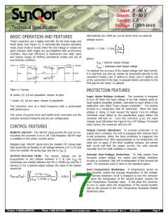
Figure 3: Maximum output power derating curve with a controlled
Figure 4: Test set-up diagram showing measurement points for Input
baseplate temperature of 80ºC and 100ºC.
Terminal Ripple Voltage (Figure 5), and Output Voltage Ripple (Figure 6).
60 Vout
48 Vout
60 Vout
48 Vout
24 Vout
12 Vout
24 Vout
12 Vout
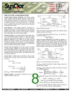
Figure 6: Output Voltage Ripple at 36 V input voltage and rated load
current (100 mV/div). Zero load capacitance. Bandwidth: 20 MHz. See
Figure 4.
Figure 5: Input Terminal Ripple Voltage at 24 V input voltage and
rated load current (500 mA/div). Bandwidth: 20 MHz. See Figure 4.
Product # NQ60x60EGC05
Phone 1-888-567-9596
www.synqor.com
Doc.# 005-NG6060W Rev. C
03/06/09
Page 5

 SYNQOR [ SYNQOR WORLDWIDE HEADQUARTERS ]