Technical
Specification
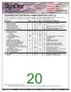
IQ18-QTC Family
BASICꢀOPERATIONꢀANDꢀFEATURES
CONTROLꢀFEATURES
Thisꢀ converterꢀ seriesꢀ usesꢀ aꢀ two-stageꢀ powerꢀ conversionꢀ
topology.ꢀ Theꢀ firstꢀ stageꢀ isꢀ aꢀ buck-converterꢀ thatꢀ keepsꢀ theꢀ
outputꢀ voltageꢀ constantꢀ overꢀ variationsꢀ inꢀ line,ꢀ load,ꢀ andꢀ
temperature.ꢀTheꢀsecondꢀstageꢀusesꢀaꢀtransformerꢀtoꢀprovideꢀ
theꢀ functionsꢀ ofꢀ input/outputꢀ isolationꢀ andꢀ voltageꢀ step-upꢀ orꢀ
step-downꢀtoꢀachieveꢀtheꢀoutputꢀvoltageꢀrequired.
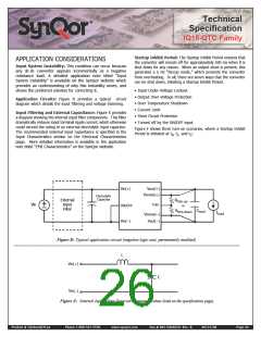
RꢁMOTꢁ Oꢀ/OFF (Pin 2):ꢀTheꢀON/OFFꢀinput,ꢀPinꢀ2,ꢀpermitsꢀ
theꢀuserꢀtoꢀcontrolꢀwhenꢀtheꢀconverterꢀisꢀonꢀorꢀoff.ꢀThisꢀinputꢀ
isꢀ referencedꢀ toꢀ theꢀ returnꢀ terminalꢀ ofꢀ theꢀ inputꢀ bus,ꢀ Vin(-).ꢀ
TheꢀON/OFFꢀsignalꢀisꢀactiveꢀlowꢀ(meaningꢀthatꢀaꢀlowꢀturnsꢀtheꢀ
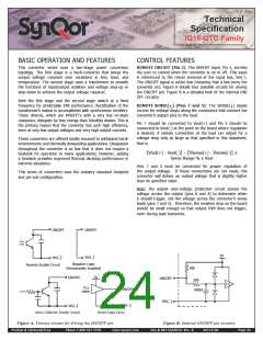
converterꢀon).ꢀFigureꢀAꢀdetailsꢀfourꢀpossibleꢀcircuitsꢀforꢀdrivingꢀ
theꢀON/OFFꢀpin.ꢀFigureꢀBꢀisꢀaꢀdetailedꢀlookꢀofꢀtheꢀinternalꢀON/
OFFꢀcircuitry.
Bothꢀ theꢀ firstꢀ stageꢀ andꢀ theꢀ secondꢀ stageꢀ switchꢀ atꢀ aꢀ fixedꢀ
frequencyꢀforꢀpredictableꢀEMIꢀperformance.ꢀRectificationꢀofꢀtheꢀ
transformer’sꢀoutputꢀisꢀaccomplishedꢀwithꢀsynchronousꢀrectifiers.ꢀ
Theseꢀ devices,ꢀ whichꢀ areꢀ MOSFETsꢀ withꢀ aꢀ veryꢀ lowꢀ on-stateꢀ
resistance,ꢀdissipateꢀfarꢀlessꢀenergyꢀthanꢀSchottkyꢀdiodes.ꢀThisꢀisꢀ
theꢀprimaryꢀreasonꢀthatꢀtheꢀconverterꢀhasꢀsuchꢀhighꢀefficiency,ꢀ
evenꢀatꢀveryꢀlowꢀoutputꢀvoltagesꢀandꢀveryꢀhighꢀoutputꢀcurrents.
RꢁMOTꢁ SꢁꢀSꢁ(+) (Pins 7 and 5):ꢀ Theꢀ SENSE(+)ꢀ inputsꢀ
correctꢀforꢀvoltageꢀdropsꢀalongꢀtheꢀconductorsꢀthatꢀconnectꢀtheꢀ
converter’sꢀoutputꢀpinsꢀtoꢀtheꢀload.
Pinꢀ 7ꢀ shouldꢀ beꢀ connectedꢀ toꢀ Vout(+)ꢀ andꢀ Pinꢀ 5ꢀ shouldꢀ beꢀ
connectedꢀtoꢀVout(-)ꢀatꢀtheꢀpointꢀonꢀtheꢀboardꢀwhereꢀregulationꢀ
isꢀ desired.ꢀ Aꢀ remoteꢀ connectionꢀ atꢀ theꢀ loadꢀ canꢀ adjustꢀ forꢀ aꢀ
voltageꢀdropꢀonlyꢀasꢀlargeꢀasꢀthatꢀspecifiedꢀinꢀthisꢀdatasheet,ꢀ
thatꢀisꢀ
Theseꢀconvertersꢀareꢀofferedꢀtotallyꢀencasedꢀtoꢀwithstandꢀharshꢀ
environmentsꢀandꢀthermallyꢀdemandingꢀapplications.ꢀDissipationꢀ
throughoutꢀ theꢀ converterꢀ isꢀ soꢀ lowꢀ thatꢀ itꢀ doesꢀ notꢀ requireꢀ aꢀ
heatsinkꢀ forꢀ operationꢀ inꢀ manyꢀ applications;ꢀ however,ꢀ addingꢀ
aꢀheatsinkꢀprovidesꢀimprovedꢀthermalꢀderatingꢀperformanceꢀinꢀ
extremeꢀsituations.
[Vout(+)ꢀ-ꢀVout(-)]ꢀ–ꢀ[Vsense(+)ꢀ-ꢀVsense(-)]ꢀ<ꢀ
SenseꢀRangeꢀ%ꢀxꢀVout
Pinsꢀ 7ꢀ andꢀ 5ꢀ mustꢀ beꢀ connectedꢀ forꢀ properꢀ regulationꢀ ofꢀ
theꢀ outputꢀ voltage.ꢀ ꢀ Ifꢀ theseꢀ connectionsꢀ areꢀ notꢀ made,ꢀ theꢀ
converterꢀ willꢀ deliverꢀ anꢀ outputꢀ voltageꢀ thatꢀ isꢀ slightlyꢀ higherꢀ
thanꢀitsꢀspecifiedꢀvalue.
Thisꢀ seriesꢀ ofꢀ convertersꢀ usesꢀ theꢀ industryꢀ standardꢀ footprintꢀ
andꢀpin-outꢀconfiguration.
Note:ꢀ theꢀ outputꢀ over-voltageꢀ protectionꢀ circuitꢀ sensesꢀ theꢀ
voltageꢀ acrossꢀ theꢀ outputꢀ (pinsꢀ 8ꢀ andꢀ 4)ꢀ toꢀ determineꢀ whenꢀ
itꢀshouldꢀtrigger,ꢀnotꢀtheꢀvoltageꢀacrossꢀtheꢀconverter’sꢀsenseꢀ
leadsꢀ(pinsꢀ7ꢀandꢀ5).ꢀꢀTherefore,ꢀtheꢀresistiveꢀdropꢀonꢀtheꢀboardꢀ
shouldꢀbeꢀsmallꢀenoughꢀsoꢀthatꢀoutputꢀOVPꢀdoesꢀnotꢀtrigger,ꢀ
evenꢀduringꢀloadꢀtransients.
ON/OFF
ON/OFF
5V
_
_
Vin( )
Vin( )
NegativeꢀLogic
(PermanentlyꢀEnabled)
RemoteꢀEnableꢀCircuit
50k
5V
ON/OFF
ON/OFF
50k
TTL
TTL/
CMOS
ON/OFF
100pF
_
Vin( )
_
_
Vin( )
Vin( )
OpenꢀCollectorꢀEnableꢀCircuit
DirectꢀLogicꢀDrive
Figure A: Various circuits for driving the ON/OFF pin.
Figure B: Internal ON/OFF pin circuitry
Product # IQ18xxxQTCxx
Phone 1-888-567-9596
www.synqor.com
Doc.# 005-IQ18QTX Rev. B
09/23/08
Page 24

 SYNQOR [ SYNQOR WORLDWIDE HEADQUARTERS ]