9-36 V
48 V
2A
Input:
Output:
Current:
Part ꢀo.:
IQ18480QTC02
Technical Specification
100
95
90
85
80
75
70
65
60
16
14
12
10
8
6
4
9 Vin
9 Vin
18 Vin
36 Vin
18 Vin
36 Vin
2
0
0.0
0.5
1.0
1.5
2.0
0.0
0.5
1.0
1.5
2.0
Load Current (A)
Load Current (A)
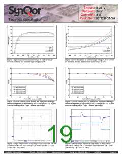
Figure 1: Efficiency at nominal output voltage vs. load current for
Figure 2: Power dissipation at nominal output voltage vs. load current
minimum, nominal, and maximum input voltage at 25
°C.
for minimum, nominal, and maximum input voltage at 25°C.
2.5
2.0
1.5
2.5
2.0
1.5
1.0
1.0
400 LFM (2.0 m/s)
400 LFM (2.0 m/s)
300 LFM (1.5 m/s)
300 LFM (1.5 m/s)
0.5
0.5
200 LFM (1.0 m/s)
200 LFM (1.0 m/s)
100 LFM (0.5 m/s)
100 LFM (0.5 m/s)
0.0
0.0
0
25
40
55
70
85
0
25
40
55
70
85
Ambient Air Temperature (°C)
Ambient Air Temperature (°C)
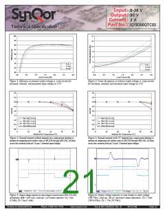
Figure 3: Encased converter (without heatsink) max. output power derating vs.
ambient air temperature for airflow rates of 100 LFM through 400 LFM. Air flows
across the converter from pin 3 to pin 1 (nominal input voltage).
Figure 4: Encased converter (with 1/4” heatsink) max. output power derating vs.
ambient air temperature for airflow rates of 100 LFM through 400 LFM. Air flows
across the converter from pin 3 to pin 1 (nominal input voltage).
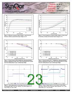
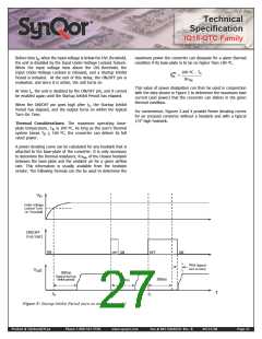
Figure 5: Output voltage response to step-change in load current (50%-75%-
Figure 6: Output voltage response to step-change in input voltage
50% of Iout(max); dI/dt = 0.02 A/µs). Load cap: 1
µF ceramic capacitor. Ch 1:
(300 V/ms). Load cap: 100 µF, electrolytic output capacitance. Ch 1: Vout
Vout (5 V/div), Ch 2: Iout (1 A/div).
(500 mV/div), Ch 2: Vin (10 V/div).
Product # IQ18xxxQTCxx
Phone 1-888-567-9596
www.synqor.com
Doc.# 005-IQ18QTX Rev. B
09/23/08
Page 23

 SYNQOR [ SYNQOR WORLDWIDE HEADQUARTERS ]