SyncMOS Technologies International, Inc.
SM89T16R1
8-Bits Micro-controller
With 64KB Flash ROM & 1KB RAM & Two UART & RTC & ADC & PWM embedded
PROG.
ADDR.
IRQ
ACC
CONTROL
PROGRAM
LOGIC
RES
TMP2
Timing & Reset
ADDR.REGISTER
TMP1
CLK
BUFFER
CTRL.
BUS
PROGRAM
INSTRUCTION
DECODER
INCREMENT
ALU
SP
PROGRAM
COUNTER
B
INSTRUCTION
REGISTER
PSW
DPTR
DATA
IN/OUT
POWER CTRL Signal
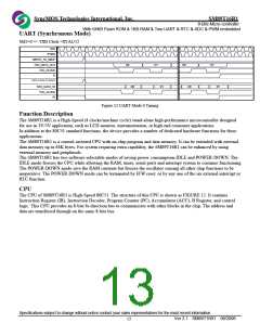
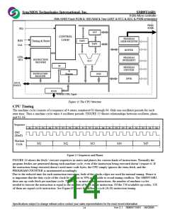
Figure 12 The CPU Structure
CPU Timing
The machine cycle consists of a sequence of 4 states, numbered S1 through S4. Only one-oscillator periods for each
state time. Thus a machine cycle takes 4 oscillator periods. FIGURE 13 Shows relationships between oscillator, phase,
and S1-S4.
Sequence
S1
S2
S4
S1
S2
S4
S1
S2
S4
S1
S2
S4
S1
S2
S4
OSC
(Xtal2)
Machine
Cycle
M1
M2
M3
M4
M5
Figure 13 Sequences and Phases
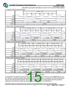
FIGURE 14 shows the fetch / execute sequences in states and phases for various kinds of instructions. Normally the
program fetches are generated during each machine cycle, even if the instruction being executed doesn’t require it. If
the instruction being executed doesn’t need more code bytes, the CPU simply ignores the extra fetch, and the
PROGRAM COUNTER is incremented accordingly.
Due to the reduced time for each instruction execution, both of the clocks edges are used for internal timing. Hence it
is important that the duty cycle of the clock be as close to 50% as possible to avoid timing conflicts. The SM89T16R1
dose one op-code fetch per machine cycle. Therefore, in most of the instructions, the number of machine cycles
needed to execute the instruction is equal to the number of bytes in the instruction. Of the 256 available op-codes, 128
of them are signal cycle instruction. See Figure14 shows the different cycle (A-D) instruction timing.
Specifications subject to change without notice contact your sales representatives for the most recent information.
Ver 2.1 SM89T16R1 08/2006
14

 SYNCMOS [ SYNCMOS TECHNOLOGIES,INC ]