MD0105
Block Diagram
COM
Switch Control
A
B
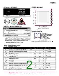
Typical I-V Characteristics
+IPEAK
IA-B
IA-B = +200µA
+1.0mA
-VOFF -VTRIP
-130V
+VTRIP +VOFF
VA-B
+130V
+1.0mA
IA-B = -200µA
RSW = 15Ω
-IPEAK
and the voltage drop across terminal A and B will be less
than ±2.0V, so the switch will remain in the closed position.
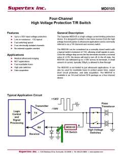
Functional Description
The Supertex MD0105 can be considered as a normally
closed switch controlled by a switch control (please refer to
the block diagram). The switch control monitors the voltage
drop across terminals A and B. If the voltage difference is
greater than ±2.0V, the T/R switch will start to open. Once
in the open state, there is a small amount of current flowing
through the T/R switch, 200µA, to detect if the high voltage
is still present or not.
The MD0105 does not require any power supply. There are
only two active pins; one connects to the transmitter side,
one connects to the receiver side.
On Resistance
When the voltage across terminals A and B are below ±2.0V,
the switch is in the receive mode and the RON is typically 15Ω.
The T/R switch will not close until the voltage across termi- Once the voltage across the terminals A and B is greater
nal A and B drops below ±2.0V. A pair of back-to-back di- than ±2.0V, the switch is in the transmit mode and blocking
odes from the receive side of the switch to ground is needed the high voltage pulses from passing through to the receiver
to complete the circuit and to allow the initial peak current and damaging it.
(about 60mA) to flow through the switch so it can drop ±2.0V.
If the diodes are not present, then there is no current path
Supertex inc. ● 1235 Bordeaux Drive, Sunnyvale, CA 94089 ● Tel: 408-222-8888 ● www.supertex.com
3

 SUPERTEX [ Supertex, Inc ]