Step 1. Calculating L1.
Step 6. Selecting input capacitor CIN
Output Power = 41V ⋅ 20mA = 820mW
The output voltage VO = 10 ·
VF ≈ 41V (max.). Use equation
(1) assuming a 30% peak-to-peak ripple.
Select CIN ECQ-E4104KF by Panasonic (0.1µF, 400V,
Metalized Polyester Film).
41V ⋅10µs
0.3⋅ 20mA
L1=
= 68mH
Design Example 2
Select L1 68mH, I=30mA. Typical SRF = 170KHz. Calculate
the coil capacitance.
Let us now design a PWM-dimmable LED lamp driver using
the HV9925:
1
1
CL =
=
≈ 13pF
L1⋅(2π ⋅SRF)2 68mH⋅(2π ⋅170KHz)2
Input:
Output Current: 50mA
Load:
String of 12 LED (Power TOPLED® by
OSRAM, VF = 2.5V max. each)
Universal AC, 85-135VAC
Step 2. Selecting D1
Usually, the reverse recovery characteristics of ultra-
fast rectifiers at IF = 20~50mA are not provided in the
manufacturer’s data books. The designer may want to
experiment with different diodes to achieve the best result.
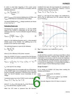
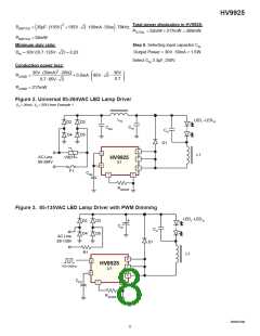
The schematic diagram of the LED driver is shown in Fig.3.
We will use an aluminum electrolytic capacitor for CIN in order
to prevent interruptions of the LED current at zero crossings
of the input voltage. As a“rule of thumb”, 2~3μF per each
watt of the input power is required for CIN in this case.
Select D1 MUR160 with VR = 600V, trr ≈ 20ns (IF = 20mA, IRR
= 100mA) and CJ ≈ 8pF (VF>50V).
Step 1. Calculating L1.
Step 3. Calculating total parasitic capacitance using:
The output voltage VO = 12 · VF = 30V (max.). Use equation
(1) assuming a 30% peak-to-peak ripple.
30V ⋅10.5µs
(3)
CP = 5pF + 5pF +13pF + 8pF = 31pF
L1=
= 21mH
Step 4. Calculating the leading edge spike duration using:
(4), (5)
0.3⋅50mA
Select L1 22mH, I = 60mA. Typical SRF = 270KHz. Calculate
the coil capacitance.
264V ⋅ 2 ⋅31pF
TSPIKE
=
+ 20ns ≈ 136ns < TBLANK(MIN)
100mA
1
1
CL =
=
≈ 15pF
L1⋅(2π ⋅SRF)2 22mH⋅(2π ⋅ 270KHz)2
Step 5. Estimating power dissipation in HV9925 at 264VAC
using (8) and (10)
Step 2. Selecting D1
Select D1 ES1G with VR = 400V, trr ≈ 35ns and CJ < 10pF.
Let us assume that the overall efficiency η = 0.7.
Switching power loss:
Step 3. Calculating total parasitic capacitance using: (3)
CP = 5pF + 5pF +13pF + 8pF = 31pF
1
41V
0.7
PSWITCH
≈
264V ⋅31pF + 2⋅100mA ⋅ 20ns 264V −
(
)
2⋅10µs
PSWITCH ≈ 125mW
Step 4. Calculating the leading edge spike duration using
(4), (5)
Minimum duty ratio:
135V ⋅ 2 ⋅35pF
TSPIKE
=
+ 35ns ≈ 100ns < TBLANK(MIN)
100mA
Dm = 0.71⋅ 41V /(0.7⋅ 264V) ≈ 0.16
Step 5. Estimating power dissipation in HV9925 at 135VAC
using (6), (7) and (9)
Conduction power loss:
PCOND = 0.25⋅ 20mA 2 ⋅ 210Ω + 0.63⋅ 200µA ⋅ 264V ≈ 55mW
(
)
Switching power loss:
Total power dissipation at VAC(max)
:
135V ⋅ 2 − 30V /0.7
FS =
= 78kHz
135V ⋅ 2 ⋅10µs
PTOTAL = 125mW + 55mW = 180mW
NR021506
7

 SUPERTEX [ Supertex, Inc ]