HV7802
Block Diagram
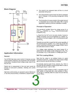
► The current to be measured does not flow in a circuit
associated with ground.
VSENSE
ISENSE
RSENSE
► The measurement at ground level can lead to ambiguity
due to changes in the grounding arrangement during
field use.
RP
(Optional,
see text)
► The introduction of a sense resistor in the system ground
is undesirable due to issues with safety, EMI, or signal
degradation caused by common impedance coupling.
RA
RA
LOAD
IN
Principle of Operation
The operational amplifier forces the voltage across RA to
track V
, therefore, VRA = VSENSE. Transconductance gain
is equaSlEtNoSE(1/RA).
Bias
Circuits
IRA flows from the OUT pin to low side circuitry. Current to
voltage conversion can be accomplished by a resistor, R ,
as shown in the block diagram, with a transimpedance gaiBn
equal to RB.
HV7802
GND
OUT
Typically we would like to exploit the full current capability of
the transimpedance amplifier. A RA of 5kΩ will provide this
current, assuming a full scale sense voltage of 500mV and a
full scale sense current of 100µA.
VOUT
R
B
In a voltage output application, the output resistor RB is
determined by the desired overall voltage gain of (R / RA).
For example, a RB of 10kΩ results in a voltage gain oBf two.
Application Information
OUT Pin Loading Effects
General
Note that the output is not buffered having an output
impedance equal to RB. Loading of the output causes voltage
gain to drop and rise and fall times to increase.
The HV7802 high side current monitor IC features accurate
current sensing, small size, low component count, low power
consumption, exceptional input voltage range, ease of use
and low cost.
For example, assume a gain of one, using R = R = 5kΩ. In
this case the load resistance should exceed 5A MΩBin order to
limit the gain drop to 1 part in 1000.
Typical use is measurement of line and load current for
purpose of overcurrent protection, metering and current
regulation.
Assuming an output resistance of 5kΩ, a capacitive load of
20pF results in a load pole with a time constant of 100ns,
not enough to materially affect the output rise and fall time
(about 700ns).
High side current sensing, as opposed to ground referenced
or low side current sensing, is desirable or required when:
3

 SUPERTEX [ Supertex, Inc ]