SMS44
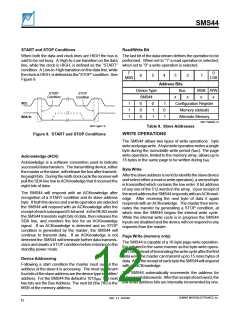
START and STOP Condi ti ons
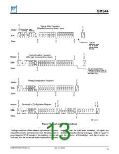
Read/ Wri te Bi t
When both the data and clock lines are HIGH the bus is The last bit of the data stream defines the operation to be
said to be not busy. A High-to-Low transition on the data performed. When set to “1” a read operation is selected;
line, while the clock is HIGH, is defined as the “START” when set to “0” a write operation is selected.
condition. A Low-to-High transition on the data line, while
7
MSB
0
LSB
theclockisHIGH,isdefinedasthe“STOP”condition. See
Figure 9.
6
5
4
3
2
1
A ddress Bits
Bus
Device Type
SMS44
MSB R/W
START
Condition
STOP
Condition
x
x
x
x
SCL
1
1
1
0
0
0
0
1
1
1
0
1
Configuration Register
Memory (default)
SDA I n
Alternate Memory
2047 Table09 1.0
2047 Fig09 1.0
Table 9.
Slave Addresses
WRI TE OPERATI ON S
Fi gure 9.
START and STOP Condi ti ons
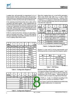
The SMS44 allows two types of write operations: byte
writeandpagewrite. Abytewriteoperationwritesasingle
byte during the nonvolatile write period (tWR). The page
write operation, limited to the memory array, allows up to
Acknowledge ( ACK)
16 bytes in the same page to be written during tWR
.
Acknowledge is a software convention used to indicate
successful data transfers. The transmitting device, either
the master or the slave, will release the bus after transmit-
tingeightbits. Duringtheninthclockcyclethereceiverwill
pull the SDA line low to ACKnowledge that it received the
eight bits of data.
By te Wri te
Aftertheslaveaddressissent(toidentifytheslavedevice
and select either a read or write operation), a second byte
is transmitted which contains the low order 8 bit address
of any one of the 512 words in the array. Upon receipt of
the word address the SMS44 responds with an ACKnowl-
edge. After receiving the next byte of data it again
responds with an ACKnowledge. The master then termi-
nates the transfer by generating a STOP condition, at
which time the SMS44 begins the internal write cycle.
While the internal write cycle is in progress the SMS44
inputs are disabled and the device will not respond to any
requests from the master.
The SMS44 will respond with an ACKnowledge after
recognition of a START condition and its slave address
byte. If both the device and a write operation are selected
the SMS44 will respond with an ACKnowledge after the
receiptofeachsubsequent8-bitword. IntheREADmode
the SMS44 transmits eight bits of data, then releases the
SDA line, and monitors the line for an ACKnowledge
signal. If an ACKnowledge is detected and no STOP
condition is generated by the master, the SMS44 will
continue to transmit data. If an ACKnowledge is not
detected the SMS44 will terminate further data transmis-
sionsandawaitsaSTOPconditionbeforereturningtothe
standby power mode.
Page Wri te ( memory only )
The SMS44 is capable of a 16-byte page write operation.
It is initiated in the same manner as the byte-write opera-
tion,butinsteadofterminatingthewritecycleafterthefirst
data word the master can transmit up to 15 more bytes of
data. AfterthereceiptofeachbytetheSMS44willrespond
with an ACKnowledge.
Devi ce Addressi ng
Following a start condition the master must output the
address of the slave it is accessing. The most significant
fourbitsoftheslaveaddressarethedevicetypeidentifier/
address. For the SMS44 the default is 1010BIN. The next
two bits are the Bus Address. The next bit (the 7th) is the
MSB of the memory address.
The SMS44 automatically increments the address for
subsequentdatawords. Afterthereceiptofeachword,the
low order address bits are internally incremented by one.
SUMMIT MICROELECTRONICS, Inc.
2047 2.3 10/23/00
12

 SUMMIT [ SUMMIT MICROELECTRONICS, INC. ]