VIPer22A-E, VIPer22ADIP-E, VIPer22AS-E
Operations
The Power MOSFET delivers a sense current I which is proportional to the main current Id.
s
R2 receives this current and the current coming from the FB pin. The voltage across R2 is
then compared to a fixed reference voltage of about 0.23 V. The MOSFET is switched off
when the following equation is reached:
R2 ⋅ (IS + IFB) = 0.23V
By extracting I :
S
0.23V
IS = --------------- – IFB
R2
Using the current sense ratio of the MOSFET G :
ID
0.23V
R2
⎛
⎞
ID = GID ⋅ IS = GID ⋅ --------------- – IFB
⎝
⎠
The current limitation is obtained with the FB pin shorted to ground (V = 0 V). This leads
FB
to a negative current sourced by this pin, and expressed by:
0.23V
IFB = –---------------
R1
By reporting this expression in the previous one, it is possible to obtain the drain current
limitation I
:
Dlim
1
1
⎛
⎞
⎠
IDlim = GID ⋅ 0.23V ⋅ ------ + ------
⎝
R2 R1
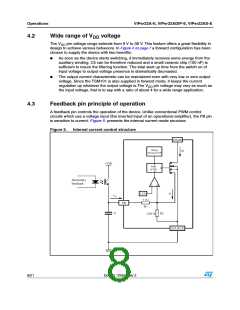
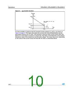
In a real application, the FB pin is driven with an optocoupler as shown on Figure 5. which
acts as a pull up. So, it is not possible to really short this pin to ground and the above drain
current value is not achievable. Nevertheless, the capacitor C is averaging the voltage on
the FB pin, and when the optocoupler is off (start up or short circuit), it can be assumed that
the corresponding voltage is very close to 0 V.
For low drain currents, the formula (1) is valid as long as IFB satisfies I < I
, where
FB
FBsd
I
is an internal threshold of the VIPer22A. If I exceeds this threshold the device will
FBsd
FB
stop switching. This is represented on Figure 12 on page 14, and I
value is specified in the
FBsd
PWM COMPARATOR SECTION. Actually, as soon as the drain current is about 12 % of
Idlim, that is to say 85 mA, the device will enter a burst mode operation by missing switching
cycles. This is especially important when the converter is lightly loaded.
Doc ID 12050 Rev 2
9/21

 STMICROELECTRONICS [ ST ]