Operations
VIPer22A-E, VIPer22ADIP-E, VIPer22AS-E
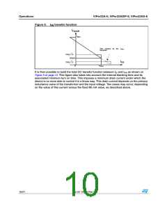
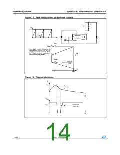
Figure 6.
I
transfer function
FB
I
Dpeak
IDlim
Part masked by the
threshold
I
FBsd
1
⋅ V
IN
t
ONmin
----------------------------------------
L
85mA
2
⋅ V
IN
t
ONmin
----------------------------------------
I
FB
L
IFBsd
0
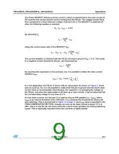
It is then possible to build the total DC transfer function between I and I as shown on
D
FB
Figure 6 on page 10. This figure also takes into account the internal blanking time and its
associated minimum turn on time. This imposes a minimum drain current under which the
device is no more able to control it in a linear way. This drain current depends on the primary
inductance value of the transformer and the input voltage. Two cases may occur, depending
on the value of this current versus the fixed 85 mA value, as described above.
10/21
Doc ID 12050 Rev 2

 STMICROELECTRONICS [ ST ]