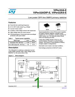
VIPer22A-E, VIPer22ADIP-E, VIPer22AS-E
Electrical data
1
Electrical data
1.1
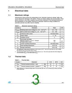
Maximum ratings
Stressing the device above the rating listed in the “absolute maximum ratings” table may
cause permanent damage to the device. These are stress ratings only and operation of the
device at these or any other conditions above those indicated in the operating sections of
this specification is not implied. Exposure to absolute maximum rating conditions for
extended periods may affect device reliability.
Table 2.
Symbol
Absolute maximum rating
Parameter
Value
Unit
VDS(sw) Switching drain source voltage (TJ = 25 ... 125 °C) (1)
VDS(st) Start-up drain source voltage (TJ = 25 ... 125 °C) (2)
-0.3 ... 730
-0.3 ... 400
Internally limited
0 ... 50
V
V
ID
Continuous drain current
Supply voltage
A
VDD
IFB
V
Feedback current
3
mA
Electrostatic discharge:
VESD
Machine model (R = 0 Ω; C = 200 pF)
Charged device model
200
1.5
V
kV
TJ
TC
Junction operating temperature
Case operating temperature
Storage temperature
Internally limited
-40 to 150
°C
°C
°C
Tstg
-55 to 150
1. This parameter applies when the start-up current source is OFF. This is the case when the VDD voltage
has reached VDDon and remains above VDDoff
.
2. This parameter applies when the start up current source is on. This is the case when the VDD voltage has
not yet reached VDDon or has fallen below VDDoff.
1.2
Thermal data
Table 3.
Symbol
Thermal data
Parameter
SO-8
25
DIP-8
15
Unit
°C/W
°C/W
RthJC
RthJA
Thermal resistance junction - case
Max
Max
Thermal resistance junction - ambient (1)
55
45
1. When mounted on a standard single-sided FR4 board with 200 mm2 of Cu (at least 35 µm thick) connected
to all DRAIN pins.
Doc ID 12050 Rev 2
3/21

 STMICROELECTRONICS [ ST ]