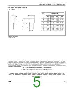
TLC116 T/D/S/A ---> TLC386 T/D/S/A
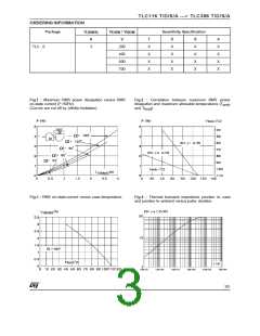
ORDERING INFORMATION
Package
I
V
/ V
DRM RRM
Sensitivity Specification
T(RMS)
A
V
T
X
X
X
X
D
X
X
X
X
S
X
X
X
X
A
X
X
X
X
TLC ..6
3
200
400
600
700
Fig.1 : Maximum RMS power dissipation versus RMS
on-state current (F=50Hz).
(Curves are cut off by (dI/dt)c limitation)
Fig.2
:
Correlation between maximum RMS power
amb
dissipation and maximum allowable temperatures (T
and T ).
lead
Fig.3 : RMS on-state current versus case temperature.
Fig.4 : Thermal transient impedance junction to case
and junction to ambient versus pulse duration.
3/5

 STMICROELECTRONICS [ ST ]