TDA8172
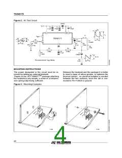
Figure 2 : AC Test Circuit
1N4001
D1
VS
C1
C2
470
C3
220 F
µ
0.1
F
µ
F
µ
t
fly
2
6
3
V7
Iy
7
1
VREF
5
TDA8172
to
R1
C4
0.22
Vi
GND
Ly
F
µ
24.6mH
to
10kΩ
R7
1.5Ω
R6
330Ω
4
RT1
4.7k
Ω
Ry
9.6
Ω
R3
R4
IN
C6
4.7
12k
8.2k
Ω
Ω
R2
5.6k
F
µ
C5
Ω
2200
F
µ
R5 Iy
R5
8.2
to
Recommended for VREF filtering
*
Ω
MOUNTING INSTRUCTIONS
The power dissipated in the circuit must be re-
moved by adding an external heatsink.
Between the heatsink and the package it is better
to insert a layer of silicon grease, to optimize the
thermal contact ; no electrical isolation is needed
between the two surfaces, since the tab is con-
nected to Pin 4 which is ground.
Thanks to the HEPTAWATTTM package attaching
the heatsinkis very simple, a screw or a compres-
sion spring (clip) being sufficient.
Figure 3 : Mounting Examples
4/5

 STMICROELECTRONICS [ ST ]