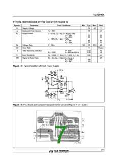
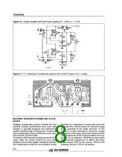
TDA2030A
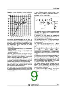
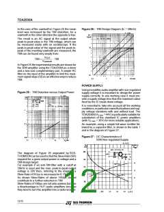
In the case of the sawtooth in Figure 25 the mean
level was increased by the TIM distortion, for a
sawtooth in the other direction the opposite is true.
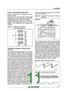
Figure 26 : TIM Design Diagram (fC = 30kHz)
The result is an AC signal at the output whole
peak-to-peak value is the TIM voltage, which can
be measured easily with an oscilloscope. If the
peak-to-peak value of the signal and the peak-to-
peak of the inverting sawtooth are measured, the
TIM can be found very simply from:
VOUT
Vsawtooth
TIM =
100
In Figure25 the experimentalresults are shown for
the 30W amplifier using the TDA2030Aas a driver
and a low-cost complementary pair. A simple RC
filter on the input of the amplifier to limit the maxi-
mumsignalslope (SS)is an effectivewayto reduce
TIM.
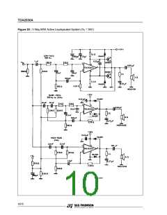
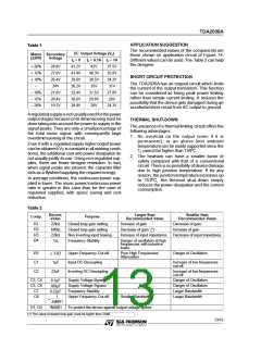
POWER SUPPLY
Usingmonolithicaudioamplifierwith non-regulated
supply voltage it is important to design the power
supply correctly. In any working case it must pro-
vide a supply voltage less than the maximum value
fixed by the IC break-down voltage.
Figure 25 : TIM Distortion versus Output Power
It is essential to take into account all the working
conditions,inparticularmainsfluctuationsand sup-
ply voltage variations with and without load. The
TDA2030A(VS max =44V) isparticularly suitablefor
substitution of the standard IC power amplifiers
(with VS max = 36V) for more reliable applications.
An example, using a simple full-wave rectifier fol-
lowed by a capacitor filter, is shown in the table 1
and in the diagram of Figure 27.
Figure 27 : DC Characteristics of
50W Non-regulated Supply
The diagram of Figure 26 originated by SGS-
THOMSON can beused to find the Slew-Rate (SR)
required for a given output power or voltage and a
TIM design target.
For example if an anti-TIM filter with a cutoff at
30kHz is used and the max. peak-to-peak output
voltage is 20V then, referring to the diagram, a
Slew-Rate of 6V/µs is necessary for 0.1% TIM.
As shown Slew-Rates of above 10V/µs do not
contribute to a further reduction in TIM.
Slew-Rates of 100/µs are not only useless but also
a disadvantage in Hi-Fi audio amplifiers because
they tend to turn the amplifier into a radio receiver.
12/15

 STMICROELECTRONICS [ ST ]