ST6208C/ST6209C/ST6210C/ST6220C
5 CLOCKS, SUPPLY AND RESET
5.1 CLOCK SYSTEM
The main oscillator of the MCU can be driven by
any of these clock sources:
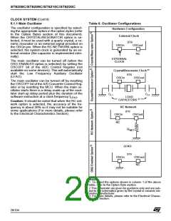
Table 6 illustrates various possible oscillator con-
figurations using an external crystal or ceramic
resonator, an external clock input, an external re-
– external clock signal
sistor (R
the LFAO.
), or the lowest cost solution using only
NET
– external AT-cut parallel-resonant crystal
– external ceramic resonator
For more details on configuring the clock options,
refer to the Option Bytes section of this document.
– external RC network (R
).
NET
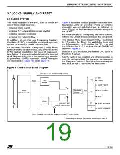
The internal MCU clock frequency (f ) is divided
In addition, an on-chip Low Frequency Auxiliary
Oscillator (LFAO) is available as a back-up clock
system or to reduce power consumption.
INT
by 12 to drive the Timer, the Watchdog timer and
the A/D converter, by 13 to drive the CPU core and
the SPI and by 1 or 3 to drive the ARTIMER, as
shown in Figure 9.
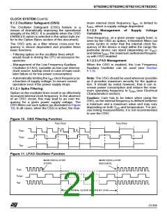
An optional Oscillator Safeguard (OSG) filters
spikes from the oscillator lines, and switches to the
LFAO backup oscillator in the event of main oscil-
lator failure. It also automatically limits the internal
With an 8 MHz oscillator, the fastest CPU cycle is
therefore 1.625µs.
clock frequency (f ) as a function of V , in order
to guarantee correct operation. These functions
are illustrated in Figure 10, and Figure 11.
INT
DD
A CPU cycle is the smallest unit of time needed to
execute any operation (for instance, to increment
the Program Counter). An instruction may require
two, four, or five CPU cycles for execution.
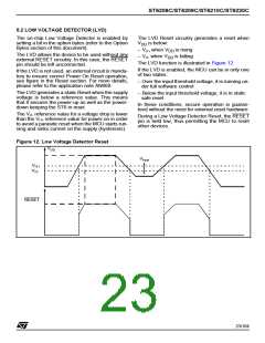
Figure 9. Clock Circuit Block Diagram
OSCILLATOR SAFEGUARD (OSG)
SPI
: 13
f
OSG
CORE
OSC
filtering
8-BIT TIMER
WATCHDOG
0
1
Oscillator
Divider
f
MAIN
OSCILLATOR
INT
: 12
*
ADC
LFAO
: 1
: 3
OSCOFF BIT
(ADCR REGISTER)
8-BIT ARTIMER
8-BIT ARTIMER
*
OSG ENABLE OPTION BIT (See OPTION BYTE SECTION)
* Depending on device. See device summary on page 1.
19/104
1

 STMICROELECTRONICS [ ST ]