ST6208C/ST6209C/ST6210C/ST6220C
4 CENTRAL PROCESSING UNIT
4.1 INTRODUCTION
tions. The accumulator can be addressed in Data
Space as a RAM location at address FFh. Thus
the ST6 can manipulate the accumulator just like
any other register in Data Space.
The CPU Core of ST6 devices is independent of the
I/O or Memory configuration. As such, it may be
thought of as an independent central processor
communicating with on-chip I/O, Memory and Pe-
ripherals via internal address, data, and control
buses.
Index Registers (X, Y). These two registers are
used in Indirect addressing mode as pointers to
memory locations in Data Space. They can also
be accessed in Direct, Short Direct, or Bit Direct
addressing modes. They are mapped in Data
Space at addresses 80h (X) and 81h (Y) and can
be accessed like any other memory location.
4.2 MAIN FEATURES
■ 40 basic instructions
Short Direct Registers (V, W). These two regis-
ters are used in Short Direct addressing mode.
This means that the data stored in V or W can be
accessed with a one-byte instruction (four CPU cy-
cles). V and W can also be accessed using Direct
and Bit Direct addressing modes. They are
mapped in Data Space at addresses 82h (V) and
83h (W) and can be accessed like any other mem-
ory location.
■ 9 main addressing modes
■ Two 8-bit index registers
■ Two 8-bit short direct registers
■ Low power modes
■ Maskable hardware interrupts
■ 6-level hardware stack
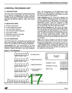
4.3 CPU REGISTERS
Note: The X and Y registers can also be used as
Short Direct registers in the same way as V and W.
The ST6FamilyCPUcorefeaturessixregistersand
three pairs of flags available to the programmer.
These are described in the following paragraphs.
Program Counter (PC). The program counter is a
12-bit register which contains the address of the
next instruction to be executed by the core. This
ROM location may be an opcode, an operand, or
the address of an operand.
Accumulator (A). The accumulator is an 8-bit
general purpose register used in all arithmetic cal-
culations, logical operations, and data manipula-
Figure 7. CPU Registers
7
0
ACCUMULATOR
SIX LEVEL
STACK
RESET VALUE = xxh
7
0
0
X INDEX REGISTER
Y INDEX REGISTER
RESET VALUE = xxh
7
CN ZN
CI ZI
CNMI ZNMI
NORMAL FLAGS
INTERRUPT FLAGS
NMI FLAGS
RESET VALUE = xxh
7
0
0
V SHORT INDIRECT
REGISTER
RESET VALUE = xxh
7
W SHORT INDIRECT
REGISTER
RESET VALUE = xxh
11
0
PROGRAM COUNTER
RESET VALUE = RESET VECTOR @ 0FFEh-0FFFh
x = Undefined value
17/104
1

 STMICROELECTRONICS [ ST ]