ST10F276E
Register set
22
Register set
22.1
Introduction
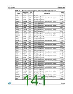
This section summarizes all registers implemented in the ST10F276E and explains the
description format used in the chapters to describe the function and layout of the SFRs. For
easy reference, the registers (except for GPRs) are sorted in two ways:
–
–
Sorted by address, to check which register is referenced by a given address.
Sorted by register name, to find the location of a specific register.
22.2
Register description format
Throughout the document, the function and the layout of the different registers is described
in a specific format. The example below explains this format.
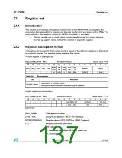
A word register is displayed as:
REG_NAME (A16h / A8h)
15 14 13 12
SFR/ESFR/XBUS
Reset value: ****h:
11
10
9
8
7
6
5
4
3
2
1
0
write hw read std
only bit only bit
hw
bit
Res. Res. Res. Res. Res.
bitfield
RW
bitfield
RW
W
RW
R
RW RW
Table 64. Description
Bit
Function
Explanation of bit(field) name
Description of the functions controlled by this bit(field).
Bit(field) name
A byte register is displayed as:
REG_NAME (A16h / A8h)
SFR/ESFR/XBUS
Reset value: - - **h:
15
-
14
-
13
-
12
-
11
-
10
-
9
-
8
-
7
6
5
4
3
2
1
0
std bithw bit
RW RW
bit field
RW
bit field
RW
Elements:
REG_NAME
A16h / A8h
This register’s name
Long 16-bit address / Short 8-bit address
SFR/ESFR/XBUS
Register space (SFR, ESFR or XBUS Register)
Register contents after reset
0/1: defined
(* *) * *
X’: undefined (undefined (’X’) after power up)
U’: unchanged
Doc ID 12303 Rev 3
137/235

 STMICROELECTRONICS [ ST ]