ST10F276E
System reset
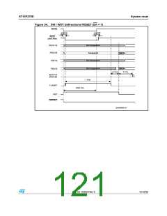
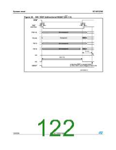
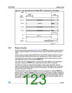
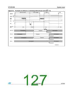
Figure 36. SW / WDT bidirectional RESET (EA = 0) followed by a HW RESET
234).
t ꢃꢉ NS
dꢃꢉꢉ NS
t ꢃꢉ NS
dꢃꢉꢉ NS
234&
ꢍAFTER FILTERꢏ
0ꢉ;ꢀꢃꢐꢀꢈ=
.OT TRANSPARENT
4RANSPARENT
0ꢉ;ꢀꢁꢐꢆ=
0ꢉ;ꢊꢐꢁ=
.OT Tꢌ
.OT TRANSPARENT
.OT TRANSPARENT
ꢀꢉꢁꢇ 4#,
.OT Tꢌ
ꢆ 4#,
0ꢉ;ꢀꢐꢉ=
!,%
234
!T THIS TIME 234& IS SAMPLED ,/7
SO (7 RESET IS ENTERED
234/54
'!0'2)ꢉꢉꢀꢀꢈ
19.7
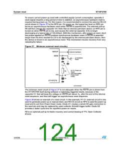
Reset circuitry
Internal reset circuitry is described in Figure 39. The RSTIN pin provides an internal pull-up
resistor of 50kΩ to 250kΩ (The minimum reset time must be calculated using the lowest
value).
It also provides a programmable (BDRSTEN bit of SYSCON register) pull-down to output
internal reset state signal (synchronous reset, watchdog timer reset or software reset).
This bidirectional reset function is useful in applications where external devices require a
reset signal but cannot be connected to RSTOUT pin.
This is the case of an external memory running codes before EINIT (end of initialization)
instruction is executed. RSTOUT pin is pulled high only when EINIT is executed.
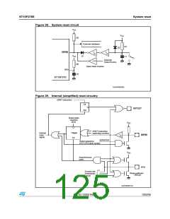
The RPD pin provides an internal weak pull-down resistor which discharges external
capacitor at a typical rate of 200μA. If bit PWDCFG of SYSCON register is set, an internal
pull-up resistor is activated at the end of the reset sequence. This pull-up will charge any
capacitor connected on RPD pin.
The simplest way to reset the ST10F276E is to insert a capacitor C1 between RSTIN pin
and VSS, and a capacitor between RPD pin and VSS (C0) with a pull-up resistor R0 between
RPD pin and VDD. The input RSTIN provides an internal pull-up device equalling a resistor of
50kΩ to 250kΩ (the minimum reset time must be determined by the lowest value). Select C1
that produce a sufficient discharge time to permit the internal or external oscillator and / or
internal PLL and the on-chip voltage regulator to stabilize.
Doc ID 12303 Rev 3
123/235

 STMICROELECTRONICS [ ST ]