CAN modules
ST10F276E
16
CAN modules
The two integrated CAN modules (CAN1 and CAN2) are identical and handle the
completely autonomous transmission and reception of CAN frames according to the CAN
specification V2.0 part B (active). It is based on the C-CAN specification.
Each on-chip CAN module can receive and transmit standard frames with 11-bit identifiers
as well as extended frames with 29-bit identifiers.
Because of duplication of the CAN controllers, the following adjustments are to be
considered:
●
Same internal register addresses of both CAN controllers, but with base addresses
differing in address bit A8; separate chip select for each CAN module. Refer to
Chapter 4: Internal Flash memory.
●
●
●
●
●
The CAN1 transmit line (CAN1_TxD) is the alternate function of the Port P4.6 pin and
the receive line (CAN1_RxD) is the alternate function of the Port P4.5 pin.
The CAN2 transmit line (CAN2_TxD) is the alternate function of the Port P4.7 pin and
the receive line (CAN2_RxD) is the alternate function of the Port P4.4 pin.
Interrupt request lines of the CAN1 and CAN2 modules are connected to the XBUS
interrupt lines together with other X-Peripherals sharing the four vectors.
The CAN modules must be selected with corresponding CANxEN bit of XPERCON
register before the bit XPEN of SYSCON register is set.
The reset default configuration is: CAN1 enabled, CAN2 disabled.
Note:
If one or both CAN modules is used, Port 4 cannot be programmed to output all 8 segment
address lines. Thus, only four segment address lines can be used, reducing the external
memory space to 5 Mbytes (1 Mbyte per CS line).
16.1
Configuration support
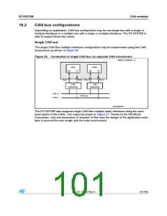
It is possible that both CAN controllers are working on the same CAN bus, supporting
together up to 64 message objects. In this configuration, both receive signals and both
transmit signals are linked together when using the same CAN transceiver. This
configuration is especially supported by providing open drain outputs for the CAN1_Txd and
CAN2_TxD signals. The open drain function is controlled with the ODP4 register for port P4:
in this way it is possible to connect together P4.4 with P4.5 (receive lines) and P4.6 with
P4.7 (transmit lines configured to be configured as Open-Drain).
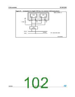
The user is also allowed to map internally both CAN modules on the same pins P4.5 and
P4.6. In this way, P4.4 and P4.7 may be used either as general purpose I/O lines, or used
for I2C interface. This is possible by setting bit CANPAR of XMISC register. To access this
register it is necessary to set bit XMISCEN of XPERCON register and bit XPEN of SYSCON
register.
100/235
Doc ID 12303 Rev 3

 STMICROELECTRONICS [ ST ]