M29F400BT, M29F400BB
Table 11. AC Measurement Conditions
Parameter
M29F400B
45 / 55
High Speed
30pF
70 / 90
Standard
100pF
AC Test Conditions
Load Capacitance (C )
L
Input Rise and Fall Times
≤ 10ns
≤ 10ns
Input Pulse Voltages
0 to 3V
1.5V
0.45 to 2.4V
0.8V and 2.0V
Input and Output Timing Ref. Voltages
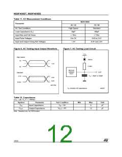
Figure 6. AC Testing Input Output Waveform
Figure 7. AC Testing Load Circuit
1.3V
High Speed
1N914
3V
1.5V
3.3kΩ
0V
DEVICE
UNDER
TEST
OUT
= 30pF or 100pF
L
Standard
C
2.4V
2.0V
0.8V
0.45V
AI01275B
C
includes JIG capacitance
AI03027
L
Table 12. Capacitance
(T = 25 °C, f = 1 MHz)
A
Symbol
Parameter
Input Capacitance
Output Capacitance
Test Condition
Min
Max
6
Unit
pF
C
V
= 0V
= 0V
IN
IN
C
OUT
V
OUT
12
pF
Note: Sampled only, not 100% tested.
12/22

 STMICROELECTRONICS [ ST ]