L6205
THERMAL DATA
Symbol
Description
PowerDIP20
SO20
14
PowerSO20
Unit
°C/W
°C/W
°C/W
R
MaximumThermal Resistance Junction-Pins
Maximum Thermal Resistance Junction-Case
12
-
-
1
-
th-j-pins
th-j-case
th-j-amb1
R
-
1
R
R
R
R
40
51
MaximumThermal Resistance Junction-Ambient
2
-
-
-
-
35
15
62
°C/W
°C/W
°C/W
th-j-amb1
th-j-amb1
th-j-amb2
Maximum Thermal Resistance Junction-Ambient
3
MaximumThermal Resistance Junction-Ambient
Maximum Thermal Resistance Junction-Ambient
4
56
77
2
(1)
(2)
(3)
Mounted on a multi-layer FR4 PCB with a dissipating copper surface on the bottom side of 6cm (with a thickness of 35µm).
2
Mounted on a multi-layer FR4 PCB with a dissipating copper surface on the top side of 6cm (with a thickness of 35µm).
Mounted on a multi-layer FR4 PCB with a dissipating copper surface on the top side of 6cm (with a thickness of 35µm), 16 via holes
2
and a ground layer.
(4)
Mounted on a multi-layer FR4 PCB without any heat sinking surface on the board.
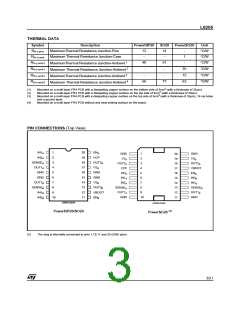
PIN CONNECTIONS (Top View)
IN1A
IN2A
1
2
3
4
5
6
7
8
9
10
20
19
18
17
16
15
14
13
12
11
ENA
GND
VSA
1
2
3
4
5
6
7
8
9
10
GND
20
19
18
17
16
15
14
13
12
11
VCP
VSB
SENSEA
OUT1A
GND
OUT2A
VSA
OUT2A
VCP
OUT2B
VBOOT
ENB
GND
GND
VSB
ENA
GND
IN1A
IN2B
OUT1B
SENSEB
IN1B
IN2A
IN1B
OUT2B
VBOOT
ENB
SENSEA
OUT1A
GND
SENSEB
OUT1B
GND
IN2B
D99IN1093A
D99IN1092A
(5)
PowerDIP20/SO20
PowerSO20
(5)
The slug is internally connected to pins 1,10,11 and 20 (GND pins).
3/21

 STMICROELECTRONICS [ ST ]