L6205
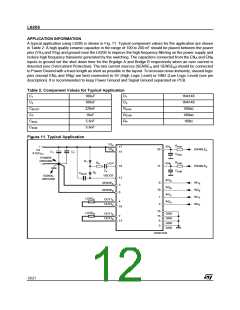
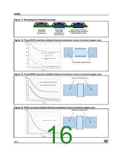
Figure 17. Mounting the PowerSO package.
Slug soldered
to PCB with
dissipating area
Slug soldered
Slug soldered to PCB with
dissipating area plus ground layer
contacted through via holes
to PCB with
dissipating area
plus ground layer
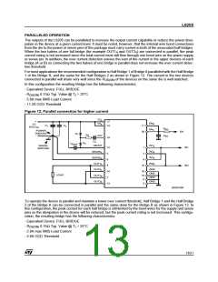
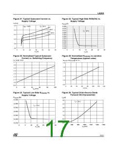
Figure 18. PowerSO20 Junction-Ambient thermal resistance versus on-board copper area.
ºC / W
43
38
33
W ithout Ground Layer
28
W ith Ground Layer
W ith Ground Layer+16 via
H oles
23
On-Board Copper Area
18
13
1
2
3
4
5
6
7
8
9
10 11 12 13
sq. cm
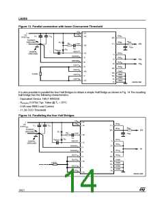
Figure 19. PowerDIP20 Junction-Ambient thermal resistance versus on-board copper area.
ºC / W
On-Board Copper Area
42
41
Copper Area is on Bottom Side
40
Copper Area is on Top Side
39
38
37
36
35
34
33
1
2
3
4
5
6
7
8
9
10 11 12
sq. cm
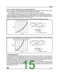
Figure 20. SO20 Junction-Ambient thermal resistance versus on-board copper area.
ºC / W
On-Board Copper Area
68
66
64
62
60
C o pp er Are a is on Top Sid e
58
56
54
52
50
48
1
2
3
4
5
6
7
8
9
10 11 12
sq. cm
16/21

 STMICROELECTRONICS [ ST ]