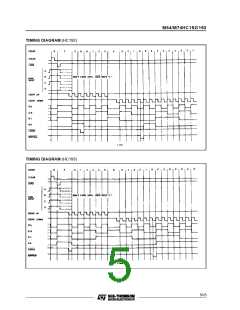
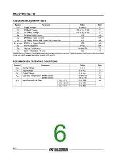
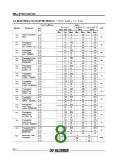
M54/M74HC192/193
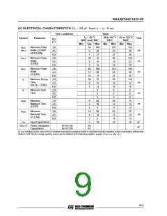
AC ELECTRICAL CHARACTERISTICS (CL = 50 pF, Input tr = tf = 6 ns)
Test Conditions
Value
-40 to 85 oC -55 to 125 oC
74HC 54HC
TA = 25 oC
54HC and 74HC
Symbol
Parameter
Unit
VCC
(V)
Min. Typ. Max. Min. Max. Min. Max.
tW(H)
tW(L)
Minimum Pulse
Width (COUNT
UP/DOWN)
2.0
4.5
6.0
2.0
4.5
6.0
2.0
4.5
6.0
2.0
4.5
6.0
2.0
4.5
6.0
2.0
4.5
6.0
2.0
4.5
6.0
34
9
100
20
17
75
15
13
100
20
17
75
15
13
0
125
25
21
95
19
16
125
25
21
95
19
16
0
150
30
26
110
22
19
150
30
26
110
22
19
0
ns
ns
ns
ns
ns
ns
ns
7
tW(L)
tW(H)
ts
Minimum Pulse
Width
(LOAD)
34
9
7
Minimum Pulse
Width
(CLEAR)
40
12
10
30
9
Minimum Set-up
Time
(DATA - LOAD)
7
th
Minimum Hold
Time
0
0
0
0
0
0
tREM
tREM
CIN
Minimum
Removal Time
(LOAD)
6
2
50
10
9
65
13
11
65
13
11
10
75
15
13
75
15
13
10
2
Minimum
Removal Time
(CLEAR)
14
4
50
10
9
3
Input Capacitance
5
10
pF
pF
CPD (*) Power Dissipation
Capacitance
for HC192
for HC193
68
67
(*) CPD isdefined as the value of the IC’s internal equivalent capacitance which is calculated from the operating current consumption without load.
(Refer to Test Circuit). Average operting current can be obtained by the followingequation. ICC(opr) = CPD • VCC • fIN + ICC
9/15

 STMICROELECTRONICS [ ST ]