S P S E M I
ꢀ ꢁ ꢂ ꢃ
TECC(1000W) Series
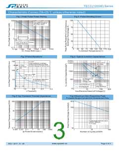
Characteristic Curves (TA=25 ℃ unless otherwise noted)
Fig.1 Peak Pulse Power Rating
Fig.2 Pulse Derating Cruve
100
75
100
10
Non-repetitive pulse
waveform shown in
Fig.3 TA = 25°C
50
1
25
0
0.31×0.31"(8.0×8.0mm)
Copper Pad Areas
0.1
10μs 100μs
0.1μs 1.0μs
td - Pulse Width (sec.)
10ms
0
25 50 75 125
100 150 175
TA-Ambient Temperature(℃)
1.0ms
200
Fig.3 Pulse Waveform
Fig.4 Typical Junction Capacitance
20000
150
100
50
TJ=25℃
Measured at
Zero Bias
10000
1000
100
Pulse width(td) is defined
ad the Point where the Peak
Current Decays to 50% of IPPM
tr=10uS
Peak Value
IPPM
IPPM
2
Half Value
VR,Measured at
Stand-Off
Voltage,VWM
10/1000μsec.Waveform
as defined by R.E.A
TJ=25℃
f=1.0MHZ
Vsig=50mVp-p
Uni-Directional
td
Bi-Directional
0
10
2.0
3.0
4.0
0
1.0
10
100
VWM-Reverse Stand-off Voltage(V)
400
1
t-Time(mS)
Fig.5 Typ.Transient Thermal Impedance
100
Fig.6 Maximum Non-Repetitive Peak
Forward Surge Current Uni-Directional Only
200
100
10
1.0
0.1
8.3mS single half sine-wave
(JEDEC Method)
TJ=TJ max.
10
1
10
100 1000
0.001 0.01 0.1
100
1
10
tp-Pulse Duration(sec)
Number of Cycles at 60HZ
Page 3 of 4
www.spsemi.cn
REV.2017.01.06

 SPSEMI [ StarHope ]