A d v a n c e I n f o r m a t i o n
the PPB and the DYB related to that sector. For the sectors that have the PPBs
cleared, the DYBs control whether or not the sector is protected or unprotected.
By issuing the DYB Write command sequences, the DYBs will be set or cleared,
thus placing each sector in the protected or unprotected state. These are the so-
called Dynamic Locked or Unlocked states. They are called dynamic states be-
cause it is very easy to switch back and forth between the protected and
unprotected conditions. This allows software to easily protect sectors against in-
advertent changes yet does not prevent the easy removal of protection when
changes are needed. The DYBs maybe set or cleared as often as needed.
The PPBs allow for a more static, and difficult to change, level of protection. The
PPBs retain their state across power cycles because they are Non-Volatile. Indi-
vidual PPBs are set with a command but must all be cleared as a group through
a complex sequence of program and erasing commands. The PPBs are limited to
100 erase cycles.
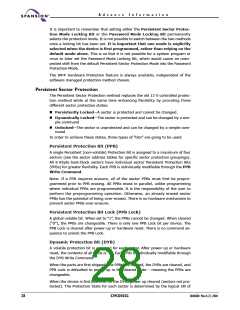
The PPB Lock bit adds an additional level of protection. Once all PPBs are pro-
grammed to the desired settings, the PPB Lock may be set to “1”. Setting the PPB
Lock disables all program and erase commands to the Non-Volatile PPBs. In ef-
fect, the PPB Lock Bit locks the PPBs into their current state. The only way to clear
the PPB Lock is to go through a power cycle. System boot code can determine if
any changes to the PPB are needed e.g. to allow new system code to be down-
loaded. If no changes are needed then the boot code can set the PPB Lock to
disable any further changes to the PPBs during system operation.
The WP# write protect pin adds a final level of hardware protection to the two
outermost 8 Kbytes sectors in the 75% bank. When this pin is low it is not pos-
sible to change the contents of these two sectors.
It is possible to have sectors that have been persistently locked, and sectors that
are left in the dynamic state. The sectors in the dynamic state are all unprotected.
If there is a need to protect some of them, a simple DYB Write command se-
quence is all that is necessary. The DYB write command for the dynamic sectors
switch the DYBs to signify protected and unprotected, respectively. If there is a
need to change the status of the persistently locked sectors, a few more steps
are required. First, the PPB Lock bit must be disabled by either putting the device
through a power-cycle, or hardware reset. The PPBs can then be changed to re-
flect the desired settings. Setting the PPB lock bit once again will lock the PPBs,
and the device operates normally again.
Note: to achieve the best protection, it’s recommended to execute the PPB lock
bit set command early in the boot code, and protect the boot code by holding
WP# = V .
IL
March 22, 2004 30606B0
S29CD032G
29

 SPANSION [ SPANSION ]