USB MultiSwitchTM Hub
Datasheet
Chapter 7 Configuration Options
7.1
Switching Hub Configuration Options
The SMSC Hub supports a large number of features (some are mutually exclusive), and must be
configured in order to correctly function when attached to a USB host controller. There are three
principal ways to configure the hub: SMBus, EEPROM, or by internal default settings (with or without
pin strapping option over-rides). In all cases, the configuration method will be determined by the
CFG_SEL2, CFG_SEL1 and CFG_SEL0 pins immediately after RESET_N negation.
7.1.1
7.1.2
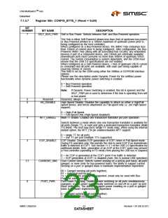
Power Switching Polarity
The selection of active state “polarity” for the PRTPWR pins is made by a strapping option only (the
PRTPWR_POL pin).
VBus Detect
According to Section 7.2.1 of the USB 2.0 Specification, a downstream port can never provide power
to its D+ or D- pull-up resistors unless the upstream port’s VBUS is in the asserted (powered) state.
The VBUS_DET pin on the Hub monitors the state of the upstream VBUS signal and will not pull-up
the D+ resistor if VBUS is not active. If VBUS goes from an active to an inactive state (Not Powered),
Hub will remove power from the D+ pull-up resistor within 10 seconds.
7.1.3
Port Assignment Configuration:
The order of precedence for control of ownership of each port is as follows:
1. CFG_SEL0 and CFG_SEL1.
2. PRT_ASSIGN_CFG register
3. PRT_ASSIGN_MODE register
4. PRT_LCK register
5. The applicable PORT_ASSIGN_INTxx or PORT_ASSIGN_xx register (based on the settings
above).
Note: The PRT_LCK register will primarily be used when in SMBus mode, but is available for use in
EEPROM Configuration, When the EEPROM port assignment values are loaded, the
PRT_LCK will be temporarily suspended, then after the configuration is loaded, the PRT_LCK
function will be enabled.
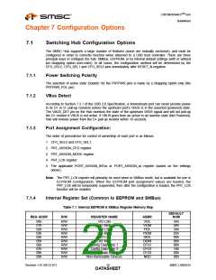
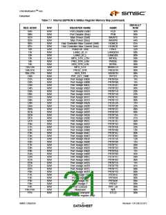
7.1.4
Internal Register Set (Common to EEPROM and SMBus)
Table 7.1 Internal EEPROM & SMBus Register Memory Map
DEFAULT
REG ADDR
R/W
REGISTER NAME
ABBR
ROM
00h
01h
02h
03h
04h
05h
06h
07h
08h
09h
R/W
R/W
R/W
R/W
R/W
R/W
R/W
R/W
R/W
R/W
VID LSB
VID MSB
PID LSB
PID MSB
DID LSB
VIDL
VIDM
PIDL
PIDM
DIDL
DIDM
CFG1
CFG2
CFG3
NRD
24h
04h
24h
25h
00h
00h
9Bh
10h
00h
00h
DID MSB
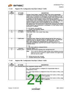
Config Data Byte 1
Config Data Byte 2
Config Data Byte 3
Non-Removable Devices
Revision 1.91 (08-22-07)
SMSC USB2524
DATA2S0HEET

 SMSC [ SMSC CORPORATION ]