USB MultiSwitchTM Hub
Datasheet
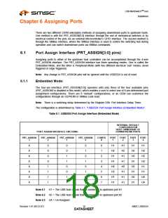
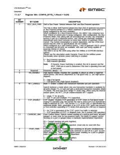
Note 6.4 X = Don’t Care
6.1.2
Peripheral Mode: Level Triggered
In Peripheral Mode (Level Triggered), each pin directly switches a downstream port between the two
upstream host ports. Each pin on the PRT_ASSIGN interface is only capable of two electrical states
(either logic low or logic high). The interface will control downstream port assignment as follows.
Note: There is a switching delay determined by the Register D0h: Port Interface Delay Timer.
PRT_ASSIGN0 = '0', then Port 1 assigned to host 1
PRT_ASSIGN0 = '1', then Port 1 assigned to host 2
PRT_ASSIGN1 = '0', then Port 2 assigned to host 1
PRT_ASSIGN1 = '1', then Port 2 assigned to host 2
PRT_ASSIGN2 = '0', then Port 3 assigned to host 1
PRT_ASSIGN2 = '1', then Port 3 assigned to host 2
PRT_ASSIGN3 = '0', then Port 4 assigned to host 1
PRT_ASSIGN3 = '1', then Port 4 assigned to host 2
6.1.3
Peripheral Mode: Edge Triggered
Each pin will respond to a positive edge transition that is part of a positive pulse that has a minimum
pulse width of 100ns, and will not respond to another positive edge until after a negative pulse with
minimum pulse width (that is determined by the Register D0h: Port Interface Delay Timer (Reset =
0x00) on page 29) has been detected. The combination of a 100ns positive pulse width and a
programmable length negative width requirement provides an effective glitch filter mechanism for a
variety of mechanical switches.
Each positive edge transition will change the upstream host ownership of downstream ports as follows
(1st transition will increment ownership from Host 1 to Host 2, the 2nd transition will increment
ownership from Host 2 to Unassigned (or Host 1, if not using the Unassigned state), and the 3rd
transition will increment ownership from Unassigned to Host 1 (note: this “3rd” state will not occur if
“unassigned” is not used). Each subsequent transition will continue to increment the port ownership
and will cycle through in similar fashion.
Note: Power-On default for edge triggered operation is: all ports assigned to Host 1.
6.2
SMBus Host Control of Port Assignment
In this mode, the SMBus interface remains “live” during operation of the switching hub and is used to
switch/assign ports “on-the-fly” through SMBus commands. This is accomplished through register
direct writes to the Port Assignment registers (see the USB_ATTACH description under Register FFh:
Status/Command (Reset = 0x00) on page 39).
SMSC USB2524
Revision 1.91 (08-22-07)
DATA1S9HEET

 SMSC [ SMSC CORPORATION ]