USB MultiSwitchTM Hub
Datasheet
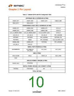
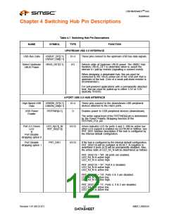
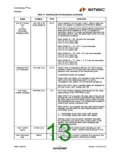
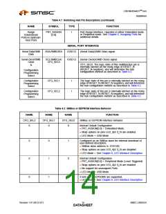
Table 4.1 Switching Hub Pin Descriptions (continued)
NAME
SYMBOL
TYPE
FUNCTION
Assign
Downstream
Ports to Upstream
Host Ports
PRT_ASSIGN
[3:0]
I
Port Assign Interface: Operates in either Embedded mode,
or Peripheral mode. See Chapter 6, Assigning Ports for
additional details.
SERIAL PORT INTERFACE
Serial Data/SMB
Data
SDA/SMBDATA
IOSD12
IOSD12
(Serial Data)/(SMB Data) signal.
Serial Clock/SMB
SCL/SMBCLK/
CFG_SEL0
(Serial Clock)/(SMB Clock) signal.
Clock
&
CFG_SEL0: The logic state of this multifunction pin is
internally latched on the rising edge of RESET_N
(RESET_N negation), and will determine the hub
configuration method as described in Table 4.2.
Configuration
Programming
Select
Configuration
Programming
Select
CFG_SEL1
CFG_SEL2
I
I
The logic state of this pin is internally latched on the rising
edge of RESET_N (RESET_N negation), and will determine
the hub configuration method as described in Table 4.2.
Configuration
Programming
Select
The logic state of this pin is internally latched on the rising
edge of RESET_N (RESET_N negation), and will determine
the hub configuration method as described in Table 4.2.
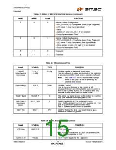
Table 4.2 SMBus or EEPROM Interface Behavior
NAME
NAME
NAME
FUNCTION
CFG_SEL2
0
CFG_SEL1
0
CFG_SEL0
0
SMBus or EEPROM interface behavior.
Internal Default Configuration
PRT_ASSIGN[3:0] = Embedded Mode.
Strap options on pins LED_A[4:1]_N are enabled.
LED Mode = USB Mode
0
0
0
1
1
0
Configured as an SMBus slave for external download of
user-defined descriptors.
SMBus slave address is :0101100
Strap options on pins LED_A[4:1]_N are disabled
LED Mode = See Chapter 8, LED Interface Description
Internal Default Configuration
PRT_ASSIGN[3:0] = Peripheral Mode (Level Triggered)
Strap options on pins LED_A[4:1]_N are enabled.
No support for unassigned Ports.
LED Mode = USB Mode
0
1
1
2-wire (I2C) EEPROMS are supported,
LED Mode = See Chapter 8, LED Interface Description
Revision 1.91 (08-22-07)
SMSC USB2524
DATA1S4HEET

 SMSC [ SMSC CORPORATION ]