USB MultiSwitchTM Hub
Datasheet
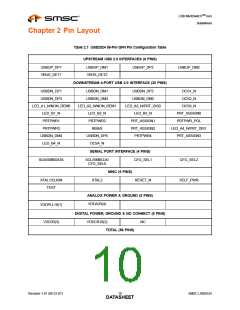
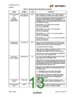
Table 4.1 Switching Hub Pin Descriptions (continued)
NAME
SYMBOL
TYPE
FUNCTION
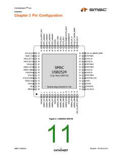
Port [2:1] Green
LED
LED_A[2:1]_N/
NON_REM[1:0]
I/O12
Green indicator LED for ports 2 and 1. Will be active low
when LED support is enabled via EEPROM or SMBus.
&
If the hub is configured by the internal default configuration,
these pins will be sampled at RESET_N negation to
determine if ports [3:1] contain permanently attached (non-
removable) devices. Also, the active state of the LED's will
be determined as follows:
Port Non-
Removable
strapping option
NON_REM[1:0] = '00', All ports are removable,
LED_A2_N is active high,
LED_A1_N is active high.
NON_REM[1:0] = '01', Port 1 is non-removable,
LED_A2_N is active high,
LED_A1_N is active low.
NON_REM[1:0] = '10', Ports 1 & 2 are non-removable,
LED_A2_N is active low,
LED_A1_N is active high.
NON_REM[1:0] = '11', Ports 1, 2, & 3 are non-removable,
LED_A2_N is active low,
LED_A1_N is active low.
Enhanced Port
LED Indicators
LED_B[4:1]_N
I/O12
These 4 pins in conjunction with the LED_A[4:1]_N pins
provides a total of 8 LED pins which are used to indicate
upstream host ownership of the downstream ports.
2 operational modes are available
Single Color LED Mode: LED will light to show which host
owns each of the downstream ports. If a port is
“unassigned” then neither LED for that port will light up.
Dual Color LED’s: (note; 4 possible states are displayed to
the user, Green, Red, Orange and Off).
Port Power
Polarity strapping
PRTPWR_POL
I/O
Port Power Polarity strapping determination for the active
signal polarity of the PRTPWR[4:1] pins.
While RESET_N is asserted, the logic state of this pin will
(through the use of internal combinatorial logic) determine
the active state of the PRTPWR[4:1] pins in order to ensure
that downstream port power is not inadvertently enabled to
inactive ports during a hardware reset.
When RESET_N is negated, the logic value will be latched
internally, and will retain the active signal polarity for the
PRTPWR[4:1] pins.
‘1’ = PRTPWR[4:1] pins have active ‘high’ polarity
‘0’ = PRTPWR[4:1] pins have active ‘low’ polarity
Warning: Active Low port power controllers may glitch
the downstream port power when system power is first
applied. Care should be taken when designing with
active low components!
Over Current
Sense
OCS[4:1]_N
RBIAS
IPU
I-R
Input from external current monitor indicating an over-
current condition. {Note: Contains internal pull-up to 3.3V
supply}
USB Transceiver
Bias
A 12.0kΩ (+/− 1%) resistor is attached from ground to this
pin to set the transceiver’s internal bias settings.
SMSC USB2524
Revision 1.91 (08-22-07)
DATA1S3HEET

 SMSC [ SMSC CORPORATION ]