USB 2.0 High-Speed 4-Port Hub Controller
Datasheet
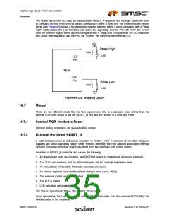
The Amber and Green LED pins are sampled after RESET_N negation, and the logic values are used
to configure the hub if the internal default configuration mode is selected. The implementation shown
below (see Figure 4.3) shows a recommended passive scheme. When a pin is configured with a “Strap
High” configuration, the LED functions with active low signalling, and the PAD will “sink” the current
from the external supply. When a pin is configured with a “Strap Low” configuration, the LED functions
with active high signalling, and the PAD will “source” the current to the external LED.
+V
Strap High
100K
LED
LED
Pin
HUB
LED
Pin
Strap Low
100K
LED
Figure 4.3 LED Strapping Option
4.7
Reset
There are two different resets that the Hub experiences. One is a hardware reset (either from the
internal POR reset circuit or via the RESET_N pin) and the second is a USB Bus Reset.
4.7.1
4.7.2
Internal POR Hardware Reset
All reset timing parameters are guaranteed by design.
External Hardware RESET_N
A valid hardware reset is defined as assertion of RESET_N for a minimum of 1us after all power
supplies are within operating range. While reset is asserted, the Hub (and its associated external
circuitry) consumes less than 500μA of current from the upstream USB power source.
Assertion of RESET_N (external pin) causes the following:
1. All downstream ports are disabled, and PRTPWR power to downstream devices is removed.
2. The PHYs are disabled, and the differential pairs will be in a high-impedance state.
3. All transactions immediately terminate; no states are saved.
4. All internal registers return to the default state (in most cases, 00(h)).
5. The external crystal oscillator is halted.
6. The PLL is halted.
7. LED indicators are disabled.
The Hub is “operational” 500μs after RESET_N is negated.
Once operational, the Hub immediately reads OEM-specific data from the external EEPROM (if the
SMBus option is not disabled).
SMSC USB2514
Revision 1.92 (05-08-07)
DATA3S5HEET

 SMSC [ SMSC CORPORATION ]