USB 2.0 High-Speed 4-Port Hub Controller
Datasheet
4.3
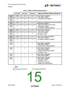
EEPROM Interface
The SMSC Hub can be configured via a 2-wire (I2C) EEPROM (256x8). (Please see Table 3.1 for
specific details on how to enable configuration via an I2C EEPROM).
The Internal state-machine will (when configured for EEPROM support) read the external EEPROM for
configuration data. The hub will then “attach” to the upstream USB host.
Note: The Hub does not have the capacity to write, or “Program,” an external EEPROM. The Hub
only has the capability to read external EEPROMs. The external eeprom will be read (even if
it is blank or non-populated), and the hub will be “configured” with the values that are read.
Please see Internal Register Set (Common to EEPROM and SMBus) for a list of data fields available.
4.3.1
Internal Register Set (Common to EEPROM and SMBus)
Table 4.2 Internal EEPROM and SMBus Register Memory Map
REG ADDR
R/W
REGISTER NAME
ABBR
DEFAULT ROM
00h
01h
02h
03h
04h
05h
06h
07h
08h
09h
0Ah
0Bh
0Ch
0Dh
0Eh
0Fh
10h
11h
R/W
R/W
R/W
R/W
R/W
R/W
R/W
R/W
R/W
R/W
R/W
R/W
R/W
R/W
R/W
R/W
R/W
R/W
R/W
R/W
R/W
R/W
R/W
VID LSB
VID MSB
VIDL
VIDM
24h
04h
14h
25h
00h
00h
9Bh
10h
00h
00h
00h
00h
01h
64h
01h
64h
32h
00h
00h
00h
00h
00h
00h
PID LSB
PIDL
PID MSB
PIDM
DID LSB
DIDL
DID MSB
DIDM
Config Data Byte 1
Config Data Byte 2
Config Data Byte 3
Non-Removable Devices
Port Disable (Self)
Port Disable (Bus)
Max Power (Self)
Max Power (Bus)
Hub Controller Max Current (Self)
Hub Controller Max Current (Bus)
Power-on Time
CFG1
CFG2
CFG3
NRD
PDS
PDB
MAXPS
MAXPB
HCMCS
HCMCB
PWRT
LANGIDH
LANGIDL
MFRSL
PRDSL
SERSL
MANSTR
LANG_ID_H
12h
13h
14h
15h
16h-53h
LANG_ID_L
MFR_STR_LEN
PRD_STR_LEN
SER_STR_LEN
MFR_STR
SMSC USB2514
Revision 1.92 (05-08-07)
DATA1S9HEET

 SMSC [ SMSC CORPORATION ]