Advanced I/O Controller with Motherboard GLUE Logic
Datasheet
CLK
1
t3 t4
CLK
2
CLK
9
CLK
10
CLK
11
KCLK/
MCLK
t5
t2
t6
t1
KDAT/ Start Bit
Bit 0
Bit 7
Parity Bit Stop Bit
MDAT
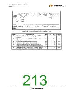
Figure 13.22 – Keyboard/Mouse Receive/Send Data Timing
NAME
t1
DESCRIPTION
Time from DATA transition to falling edge of CLOCK
MIN
5
TYP
MAX
25
UNITS
µsec
(Receive)
t2
Time from rising edge of CLOCK to DATA transition
(Receive)
5
T4-5
µsec
t3
t4
t5
Duration of CLOCK inactive (Receive/Send)
Duration of CLOCK active (Receive/Send)
30
30
>0
50
50
50
µsec
µsec
µsec
Time to keyboard inhibit after clock 11 to ensure the
keyboard does not start another transmission (Receive)
t6
Time from inactive to active CLOCK transition, used to
time when the auxiliary device samples DATA (Send)
5
25
µsec
SMSC LPC47M182
213
Revision 1.8 SMSC/Non-SMSC Register Sets (02-24-05)
DATASHEET

 SMSC [ SMSC CORPORATION ]