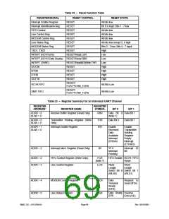
Table 32 – Reset Function Table
RESET CONTROL
REGISTER/SIGNAL
Interrupt Enable Register
Interrupt Identification Reg.
FIFO Control
RESET STATE
RESET
All bits low
RESET
Bit 0 is high; Bits 1 - 7 low
RESET
All bits low
Line Control Reg.
RESET
All bits low
MODEM Control Reg.
Line Status Reg.
RESET
RESET
All bits low
All bits low except 5, 6 high
MODEM Status Reg.
TXD1, TXD2
INTRPT (RCVR errs)
INTRPT (RCVR Data Ready) RESET/Read RBR
INTRPT (THRE)
OUT2B
RTSB
DTRB
OUT1B
RESET
RESET
RESET/Read LSR
Bits 0 - 3 low; Bits 4 - 7 input
High
Low
Low
Low
High
High
High
High
RESET/ReadIIR/Write THR
RESET
RESET
RESET
RESET
RESET/
RCVR FIFO
XMIT FIFO
All Bits Low
All Bits Low
FCR1*FCR0/_FCR0
RESET/
FCR1*FCR0/_FCR0
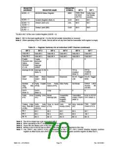
Table 33 – Register Summary for an Individual UART Channel
REGISTER
REGISTER
ADDRESS*
REGISTER NAME
SYMBOL
BIT 0
BIT 1
ADDR = 0
Receive Buffer Register (Read Only)
RBR
Data Bit 0 Data Bit 1
DLAB = 0
(Note 1)
ADDR = 0
DLAB = 0
ADDR = 1
DLAB = 0
Transmitter Holding Register (Write
Only)
Interrupt Enable Register
THR
IER
Data Bit 0
Data Bit 1
Enable
Enable
Received
Data
Transmitter
Holding
Available
Interrupt
(ERDAI)
Register
Empty
Interrupt
(ETHREI)
ADDR = 2
Interrupt Ident. Register (Read Only)
IIR
"0" if
Interrupt ID
Bit
Interrupt
Pending
ADDR = 2
ADDR = 3
FIFO Control Register (Write Only)
Line Control Register
FCR
FIFO Enable RCVR FIFO
Reset
(Note 7)
LCR
Word
Word
Length
Length
Select Bit 0 Select Bit 1
(WLS0)
(WLS1)
ADDR = 4
ADDR = 5
MODEM Control Register
MCR
LSR
Data
Request to
Send (RTS)
Terminal
Ready
(DTR)
Data Ready
Line Status Register
Overrun
(DR)
Error (OE)
SMSC DS – LPC47M14X
Page 69
Rev. 03/19/2001

 SMSC [ SMSC CORPORATION ]