REG OFFSET
(hex)
NAME
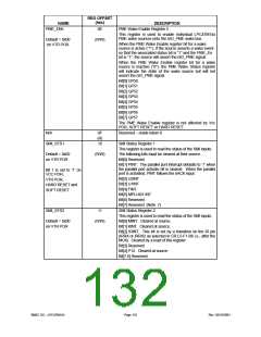
PME_EN5
DESCRIPTION
PME Wake Enable Register 5
0E
This register is used to enable individual LPC47M14x
PME wake sources onto the nIO_PME wake bus.
Default = 0x00
on VTR POR
(R/W)
When the PME Wake Enable register bit for a wake
source is active (“1”), if the source asserts a wake event
so that the associated status bit is “1” and the PME_En
bit is “1”, the source will assert the nIO_PME signal.
When the PME Wake Enable register bit for a wake
source is inactive (“0”), the PME Wake Status register
will indicate the state of the wake source but will not
assert the nIO_PME signal.
Bit[0] GP50
Bit[1] GP51
Bit[2] GP52
Bit[3] GP53
Bit[4] GP54
Bit[5] GP55
Bit[6] GP56
Bit[7] GP57
The PME Wake Enable register is not affected by Vcc
POR, SOFT RESET or HARD RESET.
Reserved – reads return 0
N/A
0F
(R)
10
SMI_STS1
SMI Status Register 1
This register is used to read the status of the SMI inputs.
The following bits must be cleared at their source.
Bit[0] Reserved
Default = 0x02
on VTR POR
(R/W)
Bit[1] PINT. The parallel port interrupt defaults to ‘1’ when
the parallel port activate bit is cleared. When the parallel
port is activated, PINT follows the nACK input.
Bit 1 is set to ‘1’ on
VCC POR,
Bit[2] U2INT
VTR POR,
Bit[3] U1INT
Bit[4] FINT
Bit[5] MPU-401 INT
Bit[6] Reserved
HARD RESET and
SOFT RESET
Bit[7] Reserved (Note 7)
SMI Status Register 2
This register is used to read the status of the SMI inputs.
Bit[0] MINT. Cleared at source.
Bit[1] KINT. Cleared at source.
SMI_STS2
11
Default = 0x00
on VTR POR
(R/W)
Bit[2] IRINT. This bit is set by a transition on the IR pin
(IRRX or IRRX2 as selected in CR L5-F1-B6 i.e., after the
MUX). Cleared by a read of this register.
Bit[3] Reserved
Bit[4] P12. Cleared at source.
Bit[7:5] Reserved
SMSC DS – LPC47M14X
Page 132
Rev. 03/19/2001

 SMSC [ SMSC CORPORATION ]