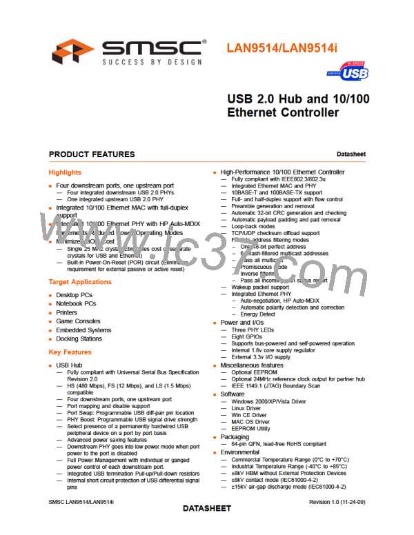
USB 2.0 Hub and 10/100 Ethernet Controller
Datasheet
Note 4.7 This is the total 5.5V input leakage for the entire device.
Note 4.8 XI can optionally be driven from a 25MHz single-ended clock oscillator.
Table 4.3 100BASE-TX Transceiver Characteristics
PARAMETER
SYMBOL
MIN
TYP
MAX
UNITS
NOTES
Peak Differential Output Voltage High
Peak Differential Output Voltage Low
Signal Amplitude Symmetry
Signal Rise and Fall Time
Rise and Fall Symmetry
Duty Cycle Distortion
VPPH
VPPL
VSS
950
-950
98
3.0
-
-
-
1050
-1050
102
5.0
mVpk
mVpk
%
Note 4.9
Note 4.9
Note 4.9
Note 4.9
Note 4.9
Note 4.10
-
TRF
-
nS
TRFS
DCD
VOS
-
0.5
nS
35
-
50
-
65
%
Overshoot and Undershoot
Jitter
5
%
1.4
nS
Note 4.11
Note 4.9 Measured at line side of transformer, line replaced by 100Ω (+/- 1%) resistor.
Note 4.10 Offset from 16nS pulse width at 50% of pulse peak.
Note 4.11 Measured differentially.
Table 4.4 10BASE-T Transceiver Characteristics
PARAMETER
SYMBOL
MIN
TYP
MAX
UNITS
NOTES
Transmitter Peak Differential Output Voltage
Receiver Differential Squelch Threshold
VOUT
VDS
2.2
2.5
2.8
V
Note 4.12
300
420
585
mV
Note 4.12 Min/max voltages guaranteed as measured with 100Ω resistive load.
Revision 1.0 (11-24-09)
SMSC LAN9514/LAN9514i
DATA4S2HEET

 SMSC [ SMSC CORPORATION ]