USB 2.0 Hub and 10/100 Ethernet Controller
Datasheet
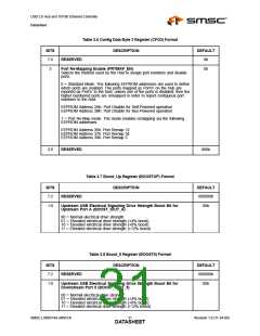
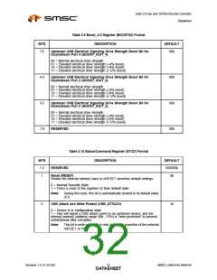
Table 3.6 Config Data Byte 3 Register (CFG3) Format
DESCRIPTION
BITS
7:4
3
DEFAULT
RESERVED
0h
0b
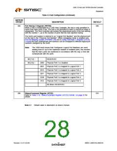
Port Re-Mapping Enable (PRTMAP_EN)
Selects the method used by the Hub to assign port numbers and disable
ports.
0 = Standard Mode. The following EEPROM addresses are used to define
which ports are enabled. The ports mapped as Port’n’ on the Hub are
reported as Port’n’ to the host, unless one of the ports is disabled, then the
higher numbered ports are remapped in order to report contiguous port
numbers to the host.
EEPROM Address 2Ah: Port Disable for Self-Powered operation
EEPROM Address 2Bh: Port Disable for Bus-Powered operation
1 = Port Re-Map mode. The mode enables remapping via the following
EEPROM addresses:
EEPROM Address 36h: Port Remap 12
EEPROM Address 37h: Port Remap 34
EEPROM Address 38h: Port Remap 5
2:0
RESERVED
000b
Table 3.7 Boost_Up Register (BOOSTUP) Format
BITS
7:2
DESCRIPTION
DEFAULT
000000b
00b
RESERVED
1:0
Upstream USB Electrical Signaling Drive Strength Boost Bit for
Upstream Port A (BOOST_IOUT_A)
00 = Normal electrical drive strength
01 = Elevated electrical drive strength (+4% boost)
10 = Elevated electrical drive strength (+8% boost)
11 = Elevated electrical drive strength (+12% boost)
Table 3.8 Boost_5 Register (BOOST5) Format
BITS
7:2
DESCRIPTION
DEFAULT
000000b
00b
RESERVED
1:0
Upstream USB Electrical Signaling Drive Strength Boost Bit for
Downstream Port 5 (BOOST_IOUT_5)
00 = Normal electrical drive strength
01 = Elevated electrical drive strength (+4% boost)
10 = Elevated electrical drive strength (+8% boost)
11 = Elevated electrical drive strength (+12% boost)
SMSC LAN9514/LAN9514i
Revision 1.0 (11-24-09)
DATA3S1HEET

 SMSC [ SMSC CORPORATION ]