USB 2.0 Hub and 10/100 Ethernet Controller
Datasheet
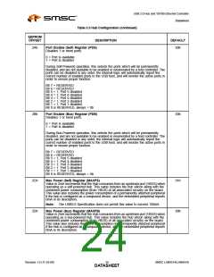
Table 3.3 Hub Configuration (continued)
EEPROM
OFFSET
DESCRIPTION
DEFAULT
2Eh
Hub Controller Max Current (Self) Register (HCMCS)
01h
Value in 2mA increments that the Hub consumes from an upstream port (VBUS) when
operating as a self-powered hub. This value includes the hub silicon along with the
combined power consumption (from VBUS) of all associated circuitry on the board.
This value does NOT include the power consumption of a permanently attached
peripheral if the hub is configured as a compound device.
Note:
The USB2.0 Specification does not permit this value to exceed 100mA.
2Fh
30h
Hub Controller Max Current (Bus) Register (HCMCB)
00h
32h
Value in 2mA increments that the Hub consumes from an upstream port (VBUS) when
operating as a bus-powered hub. This value includes the hub silicon along with the
combined power consumption (from VBUS) of all associated circuitry on the board.
This value does NOT include the power consumption of a permanently attached
peripheral if the hub is configured as a compound device.
Power-on Time Register (PWRT)
The length of time that it takes (in 2mS intervals) from the time the host initiated
power-on sequence begins on a port until power is good on that port. System software
uses this value to determine how long to wait before accessing a powered-on port.
31h
32h
33h
Boost_Up Register (BOOSTUP)
00h
00h
00h
Refer to Table 3.7, “Boost_Up Register (BOOSTUP) Format,” on page 31 for details.
Boost_5 Register (BOOST5)
Refer to Table 3.8, “Boost_5 Register (BOOST5) Format,” on page 31 for details.
Boost_4:2 Register (BOOST42)
Refer to Table 3.9, “Boost_4:2 Register (BOOST42) Format,” on page 32 for details.
34h
35h
RESERVED
00h
00h
Port Swap Register (PRTSP)
Swaps the Upstream and Downstream USB DP and DM pins for ease of board routing
to devices and connectors.
0 = USB D+ functionality is associated with the DP pin and D- functionality is
associated with the DM pin.
1 = USB D+ functionality is associated with the DM pin and D- functionality is
associated with the DP pin.
Bit 7 = RESERVED
Bit 6 = RESERVED
Bit 5 = 1; Port 5 DP/DM is swapped
Bit 4 = 1; Port 4 DP/DM is swapped
Bit 3 = 1; Port 3 DP/DM is swapped
Bit 2 = 1; Port 2 DP/DM is swapped
Bit 1 = RESERVED
Bit 0 = 1; Upstream Port DP/DM is swapped
SMSC LAN9514/LAN9514i
Revision 1.0 (11-24-09)
DATA2S5HEET

 SMSC [ SMSC CORPORATION ]