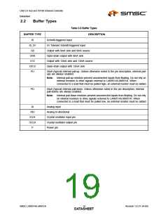
USB 2.0 Hub and 10/100 Ethernet Controller
Datasheet
3.1.1
Hub Configuration
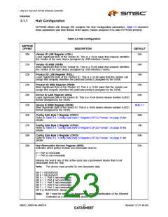
EEPROM offsets 20h through 39h comprise the Hub Configuration parameters. Table 3.3 describes
these parameters and their default ROM values (Values assumed if no valid EEPROM present).
Table 3.3 Hub Configuration
EEPROM
OFFSET
DESCRIPTION
DEFAULT
20h
21h
22h
23h
24h
25h
26h
27h
28h
29h
Vendor ID LSB Register (VIDL)
24h
Least Significant Byte of the Vendor ID. This is a 16-bit value that uniquely identifies
the Vendor of the user device (assigned by USB-Interface Forum).
Vendor ID MSB (VIDM)
Most Significant Byte of the Vendor ID. This is a 16-bit value that uniquely identifies
the Vendor of the user device (assigned by USB-Interface Forum).
04h
14h
Product ID LSB Register (PIDL)
Least Significant Byte of the Product ID. This is a 16-bit value that the Vendor can
assign that uniquely identifies this particular product (assigned by the OEM).
Product ID MSB Register (PIDM)
Most Significant Byte of the Product ID. This is a 16-bit value that the Vendor can
assign that uniquely identifies this particular product (assigned by the OEM).
95h
Device ID LSB Register (DIDL)
Least Significant Byte of the Device ID. This is a 16-bit device release number in BCD
format (assigned by the OEM).
00h
Device ID MSB Register (DIDM)
Most Significant Byte of the Device ID. This is a 16-bit device release number in BCD
format (assigned by the OEM).
Note 3.1
9Bh
Config Data Byte 1 Register (CFG1)
Refer to Table 3.4, “Config Data Byte 1 Register (CFG1) Format,” on page 29 for
details.
Config Data Byte 2 Register (CFG2)
Refer to Table 3.5, “Config Data Byte 2 Register (CFG2) Format,” on page 30 for
details.
18h
Config Data Byte 3 Register (CFG3)
Refer to Table 3.6, “Config Data Byte 3 Register (CFG3) Format,” on page 31 for
details.
00h
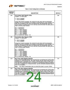
Non-Removable Devices Register (NRD)
Indicates which port(s) include non-removable devices.
02h
0 = Port is removable
1 = Port is non-removable
Informs the host if one of the active ports has a permanent device that is not
detachable from the Hub.
Note:
The device must provide its own descriptor data.
Bit 7 = RESERVED
Bit 6 = RESERVED
Bit 5 = 1; Port 5 non-removable
Bit 4 = 1; Port 4 non-removable
Bit 3 = 1; Port 3 non-removable
Bit 2 = 1; Port 2 non-removable
Bit 1 = 1; Port 1 non-removable
Bit 0 is RESERVED, always = 0b
Note:
Bit 1 must be set to 1 by firmware for proper identification of the Ethernet
Controller as a non-removable device.
SMSC LAN9514/LAN9514i
Revision 1.0 (11-24-09)
DATA2S3HEET

 SMSC [ SMSC CORPORATION ]