USB 2.0 Hub and 10/100 Ethernet Controller
Datasheet
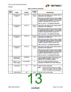
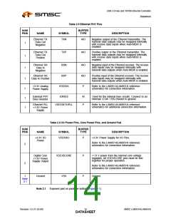
Table 2.5 Ethernet PHY Pins
NUM
PINS
BUFFER
TYPE
NAME
SYMBOL
DESCRIPTION
Ethernet TX
Data Out
Negative
TXN
AIO
AIO
AIO
Negative output of the Ethernet transmitter. The
transmit data outputs may be swapped internally
with receive data inputs when Auto-MDIX is
enabled.
1
1
Ethernet TX
Data Out
Positive
TXP
RXN
Positive output of the Ethernet transmitter. The
transmit data outputs may be swapped internally
with receive data inputs when Auto-MDIX is
enabled.
Ethernet RX
Data In
Negative
Negative input of the Ethernet receiver. The receive
data inputs may be swapped internally with
transmit data outputs when Auto-MDIX is enabled.
1
1
Ethernet RX
Data In Positive
RXP
AIO
P
Positive input of the Ethernet receiver. The receive
data inputs may be swapped internally with
transmit data outputs when Auto-MDIX is enabled.
+3.3V Analog
Power Supply
VDD33A
Refer to the LAN9514/LAN9514i reference
schematics for connection information.
7
1
1
External PHY
Bias Resistor
EXRES
AI
P
Used for the internal bias circuits. Connect to an
external 12.4K 1.0% resistor to ground.
Ethernet PLL
+1.8V Power
Supply
VDD18ETHPLL
Refer to the LAN9514/LAN9514i reference
schematics for additional connection information.
Table 2.6 I/O Power Pins, Core Power Pins, and Ground Pad
BUFFER
NUM
PINS
NAME
SYMBOL
TYPE
DESCRIPTION
+3.3V I/O
Power
VDD33IO
P
+3.3V Power Supply for I/O Pins.
Refer to the LAN9514/LAN9514i reference
schematics for connection information.
5
2
Digital Core
+1.8V Power
Supply Output
VDD18CORE
P
P
+1.8 V power from the internal core voltage
regulator. All VDD18CORE pins must be tied
together for proper operation.
Refer to the LAN9514/LAN9514i reference
schematics for connection information.
1
Ground
VSS
Ground
Note
2.1
Note 2.1 Exposed pad on package bottom (Figure 2.1).
Revision 1.0 (11-24-09)
SMSC LAN9514/LAN9514i
DATA1S4HEET

 SMSC [ SMSC CORPORATION ]