USB 2.0 Hub and 10/100 Ethernet Controller
Datasheet
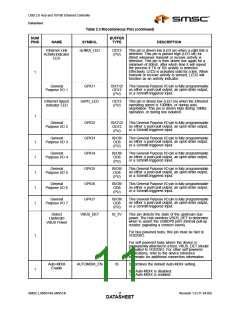
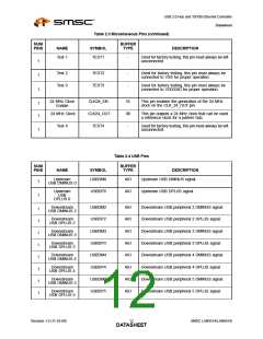
Table 2.3 Miscellaneous Pins (continued)
NUM
PINS
BUFFER
TYPE
NAME
SYMBOL
DESCRIPTION
Test 1
TEST1
-
Used for factory testing, this pin must always be left
unconnected.
1
1
1
Test 2
Test 3
TEST2
TEST3
-
-
Used for factory testing, this pin must always be
connected to VSS for proper operation.
Used for factory testing, this pin must always be
connected to VDD33IO for proper operation.
24 MHz Clock
Enable
CLK24_EN
CLK24_OUT
TEST4
IS
08
-
This pin enables the generation of the 24 MHz
clock on the CLK_24_OUT pin.
1
1
24 MHz Clock
This pin outputs a 24 MHz clock that can be used
a reference clock for a partner hub.
Test 4
Used for factory testing, this pin must always be left
unconnected.
1
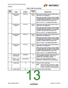
Table 2.4 USB Pins
NUM
PINS
BUFFER
TYPE
NAME
SYMBOL
DESCRIPTION
Upstream
USBDM0
AIO
AIO
Upstream USB DMINUS signal.
Upstream USB DPLUS signal.
1
1
USB DMINUS 0
Upstream
USB
DPLUS 0
USBDP0
Downstream
USBDM2
USBDP2
USBDM3
USBDP3
USBDM4
USBDP4
USBDM5
USBDP5
AIO
AIO
AIO
AIO
AIO
AIO
AIO
AIO
Downstream USB peripheral 2 DMINUS signal.
Downstream USB peripheral 2 DPLUS signal.
Downstream USB peripheral 3 DMINUS signal.
Downstream USB peripheral 3 DPLUS signal.
Downstream USB peripheral 4 DMINUS signal.
Downstream USB peripheral 4 DPLUS signal.
Downstream USB peripheral 5 DMINUS signal.
Downstream USB peripheral 5 DPLUS signal.
1
1
1
1
1
1
1
1
USB DMINUS 2
Downstream
USB DPLUS 2
Downstream
USB DMINUS 3
Downstream
USB DPLUS 3
Downstream
USB DMINUS 4
Downstream
USB DPLUS 4
Downstream
USB DMINUS 5
Downstream
USB DPLUS 5
Revision 1.0 (11-24-09)
SMSC LAN9514/LAN9514i
DATA1S2HEET

 SMSC [ SMSC CORPORATION ]