USB 2.0 Hub and 10/100 Ethernet Controller
Datasheet
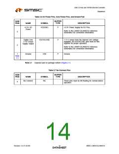
Table 2.6 I/O Power Pins, Core Power Pins, and Ground Pad
NUM
PINS
BUFFER
TYPE
NAME
SYMBOL
DESCRIPTION
+3.3V I/O
Power
VDD33IO
P
P
+3.3V Power Supply for I/O Pins.
Refer to the LAN9512/LAN9512i reference
schematics for connection information.
5
2
Digital Core
+1.8V Power
Supply Output
VDD18CORE
+1.8 V power from the internal core voltage
regulator. All VDD18CORE pins must be tied
together for proper operation.
Refer to the LAN9512/LAN9512i reference
schematics for connection information.
1
Ground
VSS
P
Ground
Note
2.1
Note 2.1 Exposed pad on package bottom (Figure 2.1).
Table 2.7 No-Connect Pins
BUFFER
NUM
PINS
NAME
SYMBOL
TYPE
DESCRIPTION
No Connect
NC
-
These pins must be left floating for normal device
operation
6
Revision 1.0 (11-24-09)
SMSC LAN9512/LAN9512i
DATA1S4HEET

 SMSC [ SMSC CORPORATION ]