USB 2.0 Hub and 10/100 Ethernet Controller
Datasheet
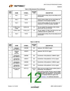
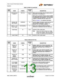
Table 2.4 USB Pins (continued)
BUFFER
NUM
PINS
NAME
SYMBOL
TYPE
DESCRIPTION
USB Port Power
Control 3
PRTCTL3
IS/OD12 When used as an output, this pin enables power to
(PU)
downstream USB peripheral 3.
When used as an input, this pin is used to sample
the output signal from an external current monitor
for downstream USB peripheral 3. An overcurrent
condition is indicated when the signal is low.
1
Refer to Section 2.1 for additional information.
External USB
Bias Resistor
USBRBIAS
VDD18USBPLL
XI
AI
P
Used for setting HS transmit current level and on-
chip termination impedance. Connect to an
external 12K 1.0% resistor to ground.
1
1
USB PLL +1.8V
Power Supply
Refer to the LAN9512/LAN9512i reference
schematics for additional connection information.
Crystal Input
ICLK
External 25 MHz crystal input.
Note:
This pin can also be driven by a single-
ended clock oscillator. When this method
is used, XO should be left unconnected
1
1
Crystal Output
XO
OCLK
External 25 MHz crystal output.
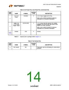
Table 2.5 Ethernet PHY Pins
NUM
PINS
BUFFER
TYPE
NAME
SYMBOL
DESCRIPTION
Ethernet TX
Data Out
Negative
TXN
AIO
AIO
AIO
Negative output of the Ethernet transmitter. The
transmit data outputs may be swapped internally
with receive data inputs when Auto-MDIX is
enabled.
1
1
Ethernet TX
Data Out
Positive
TXP
RXN
Positive output of the Ethernet transmitter. The
transmit data outputs may be swapped internally
with receive data inputs when Auto-MDIX is
enabled.
Ethernet RX
Data In
Negative
Negative input of the Ethernet receiver. The receive
data inputs may be swapped internally with
transmit data outputs when Auto-MDIX is enabled.
1
1
Ethernet RX
Data In Positive
RXP
AIO
P
Positive input of the Ethernet receiver. The receive
data inputs may be swapped internally with
transmit data outputs when Auto-MDIX is enabled.
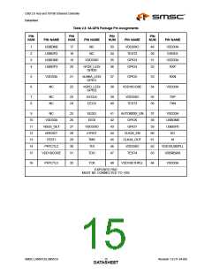
+3.3V Analog
Power Supply
VDD33A
Refer to the LAN9512/LAN9512i reference
schematics for connection information.
7
1
1
External PHY
Bias Resistor
EXRES
AI
P
Used for the internal bias circuits. Connect to an
external 12.4K 1.0% resistor to ground.
Ethernet PLL
+1.8V Power
Supply
VDD18ETHPLL
Refer to the LAN9512/LAN9512i reference
schematics for additional connection information.
SMSC LAN9512/LAN9512i
Revision 1.0 (11-24-09)
DATA1S3HEET

 SMSC [ SMSC CORPORATION ]