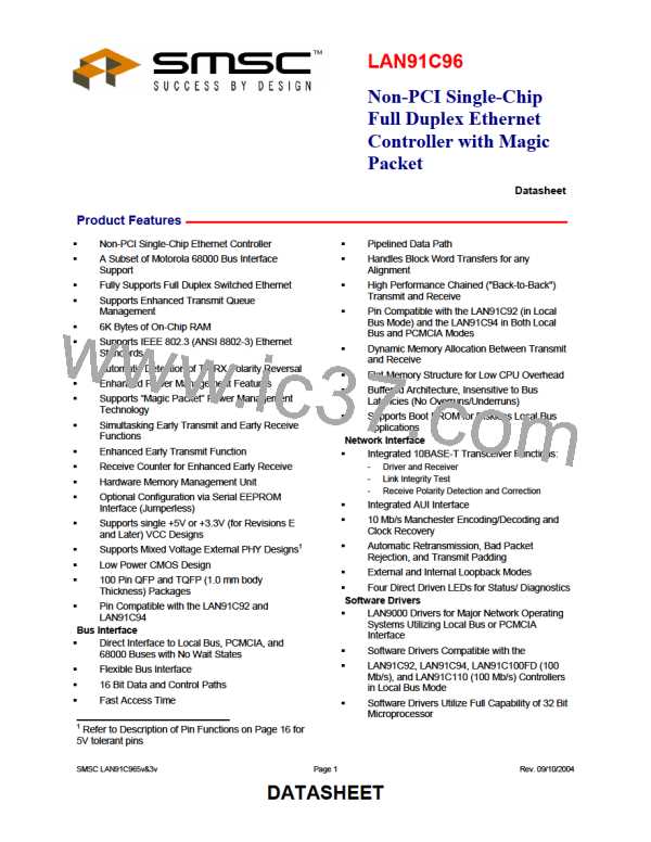
Non-PCI Single-Chip Full Duplex Ethernet Controller with Magic Packet
9.13.4 SQE Function _____________________________________________________________________________ 87
9.14
Receive Functions ___________________________________________________________________________ 87
9.14.1 Receive Drivers____________________________________________________________________________ 87
9.14.2 Manchester Decoder and Clock Recovery _______________________________________________________ 87
9.14.3 Squelch Function __________________________________________________________________________ 87
9.14.4 Reverse Polarity Function____________________________________________________________________ 88
9.14.5 Collision Detection Function _________________________________________________________________ 88
9.14.6 Link Integrity _____________________________________________________________________________ 88
Chapter 10 Board Setup Information____________________________________________________________________ 89
10.1
10.2
10.3
Diagnostic LEDs ____________________________________________________________________________ 90
Bus Clock Considerations ____________________________________________________________________ 90
68000 Bus Interface__________________________________________________________________________ 90
Chapter 11 Operational Description_____________________________________________________________________ 92
11.1
11.2
Maximum Guaranteed Ratings* _______________________________________________________________ 92
DC Electrical Characteristics _________________________________________________________________ 92
Chapter 12 Timing Diagrams __________________________________________________________________________ 99
Chapter 13 LAN91C96 Revisions______________________________________________________________________ 125
LIST OF FIGURES
Figure 3.1 - LAN91C96 100 Pin QFP...........................................................................................................................10
Figure 3.2 - LAN91C96 100 Pin TQFP.........................................................................................................................11
Figure 3.3 - LAN91C96 System Block Diagram ...........................................................................................................12
Figure 3.4 – System Diagram for Local Bus with Boot Prom .......................................................................................13
Figure 4.1 - LAN91C96 Internal Block Diagram...........................................................................................................21
Figure 5.1 – Mapping and Paging vs. Receive and Transmit Area ..............................................................................24
Figure 5.2 – Transmit Queues and Mapping................................................................................................................25
Figure 5.3 – Receive Queues and Mapping.................................................................................................................26
Figure 5.4 - LAN91C96 Internal Block Diagram with Data Path...................................................................................27
Figure 5.5 – Logical Address Generation and Relevant Registers...............................................................................28
Figure 6.1 – Data Frame Format..................................................................................................................................37
Figure 6.2 - LAN91C96 Registers ................................................................................................................................40
Figure 7.1 – Interrupt Structure.....................................................................................................................................61
Figure 8.1 – Interrupt Service Routine .........................................................................................................................70
Figure 8.2 - RX INTR ...................................................................................................................................................71
Figure 8.3 -TX INTR.....................................................................................................................................................72
Figure 8.4 -TXEMPTY INTR ........................................................................................................................................73
Figure 8.5 – Driver Send and Allocate Routines ..........................................................................................................74
Figure 8.6 – Interrupt Generation for Transmit; Receive, MMU ...................................................................................78
FIGURE 9.1 - MMU PACKET NUMBER FLOW AND RELEVANT REGISTERS.........................................................84
FIGURE 10.1 - 64 X 16 SERIAL EEPROM MAP .........................................................................................................91
Figure 12.1 – Card Configuration Registers – Read/Write PCMCIA Mode (A15=1) ....................................................99
Figure 12.2 – Local Bus Consecutive Read Cycles ...................................................................................................100
Figure 12.3 - PCMCIA Consecutive Read Cycles......................................................................................................101
Figure 12.4 – Local Bus Consecutive Write Cycles....................................................................................................102
Figure 12.5 - PCMCIA Consecutive Write Cycles ......................................................................................................103
Figure 12.6 – Local Bus Consecutive Read and Write Cycles...................................................................................104
Figure 12.7 – Data Register Special Read Access ....................................................................................................105
Figure 12.8 – Data Register Special Write Access.....................................................................................................106
Figure 12.9 - 8-Bit Mode Register Cycles ..................................................................................................................107
Figure 12.10 - 68000 Read Timing.............................................................................................................................108
Figure 12.11 - 68000 Write Timing.............................................................................................................................109
Figure 12.12 – External ROM Read Access ..............................................................................................................110
Figure 12.13 – Local Bus Register Access When Using Bale....................................................................................111
Rev. 09/10/2004
Page 4
SMSC LAN91C965v&3v
DATASHEET

 SMSC [ SMSC CORPORATION ]