Small Footprint MII/RMII 10/100 Ethernet Transceiver for Automotive Applications
Datasheet
3.4.3
MII vs. RMII Configuration
The device must be configured to support the MII or RMII bus for connectivity to the MAC. This
configuration is done via the RMIISEL configuration strap. MII or RMII mode selection is configured
based on the strapping of the RMIISEL configuration strap as described in Section 3.7.3, "RMIISEL:
MII/RMII Mode Configuration," on page 39.
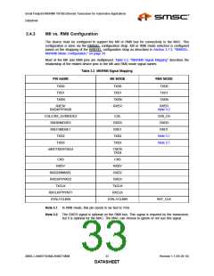
Most of the MII and RMII pins are multiplexed. Table 3.2, "MII/RMII Signal Mapping" describes the
relationship of the related device pins to the MII and RMII mode signal names.
Table 3.2 MII/RMII Signal Mapping
PIN NAME
MII MODE
RMII MODE
TXD0
TXD1
TXEN
TXD0
TXD1
TXEN
RXER
TXD0
TXD1
TXEN
RXER/
RXER
RXD4/PHYAD0
Note 3.2
COL/CRS_DV/MODE2
RXD0/MODE0
RXD1/MODE1
TXD2
COL
RXD0
RXD1
TXD2
TXD3
CRS_DV
RXD0
RXD1
Note 3.1
Note 3.1
TXD3
nINT/TXER/TXD4
TXER/
TXD4
CRS
CRS
RXDV
RXDV
RXD2/RMIISEL
RXD3/PHYAD2
TXCLK
RXD2
RXD3
TXCLK
RXCLK/PHYAD1
XTAL1/CLKIN
RXCLK
XTAL1/CLKIN
REF_CLK
Note 3.1 In RMII mode, this pin needs to be tied to VSS.
Note 3.2 The RXER signal is optional on the RMII bus. This signal is required by the transceiver,
but it is optional for the MAC. The MAC can choose to ignore or not use this signal.
SMSC LAN88710AM/LAN88710BM
33
Revision 1.1 (05-26-10)
DATASHEET

 SMSC [ SMSC CORPORATION ]