Small Footprint MII/RMII 10/100 Ethernet Transceiver for Automotive Applications
Datasheet
3.4
MAC Interface
The MII/RMII block is responsible for communication with the MAC controller. Special sets of hand-
shake signals are used to indicate that valid received/transmitted data is present on the 4 bit
receive/transmit bus.
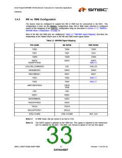
The device must be configured in MII or RMII mode. This is done by specific pin strapping
configurations. Refer to Section 3.4.3, "MII vs. RMII Configuration," on page 33 for information on pin
strapping and how the pins are mapped differently.
3.4.1
MII
The MII includes 16 interface signals:
transmit data - TXD[3:0]
transmit strobe - TXEN
transmit clock - TXCLK
transmit error - TXER/TXD4
receive data - RXD[3:0]
receive strobe - RXDV
receive clock - RXCLK
receive error - RXER/RXD4/PHYAD0
collision indication - COL
carrier sense - CRS
In MII mode, on the transmit path, the transceiver drives the transmit clock, TXCLK, to the controller.
The controller synchronizes the transmit data to the rising edge of TXCLK. The controller drives TXEN
high to indicate valid transmit data. The controller drives TXER high when a transmit error is detected.
On the receive path, the transceiver drives both the receive data, RXD[3:0], and the RXCLK signal.
The controller clocks in the receive data on the rising edge of RXCLK when the transceiver drives
RXDV high. The transceiver drives RXER high when a receive error is detected.
SMSC LAN88710AM/LAN88710BM
31
Revision 1.1 (05-26-10)
DATASHEET

 SMSC [ SMSC CORPORATION ]