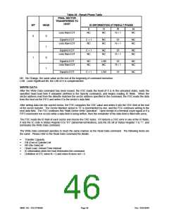
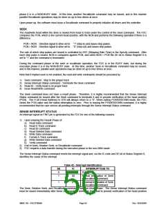
Table 38 - Result Phase Table
FINAL SECTOR
TRANSFERRED TO
HOST
MT
HEAD
ID INFORMATION AT RESULT PHASE
C
NC
H
NC
R
R + 1
N
NC
Less than EOT
0
0
1
0
1
Equal to EOT
Less than EOT
C + 1
NC
NC
NC
01
R + 1
NC
NC
Equal to EOT
Less than EOT
C + 1
NC
NC
NC
01
R + 1
NC
NC
1
Equal to EOT
Less than EOT
NC
NC
LSB
NC
01
R + 1
NC
NC
Equal to EOT
C + 1
LSB
01
NC
NC: No Change, the same value as the one at the beginning of command execution.
LSB: Least Significant Bit, the LSB of H is complemented.
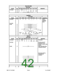
WRITE DATA
After the Write Data command has been issued, the FDC loads the head (if it is in the unloaded state), waits the
specified head load time if unloaded (defined in the Specify command), and begins reading ID fields. When the
sector address read from the diskette matches the sector address specified in the command, the FDC reads the data
from the host via the FIFO and writes it to the sector’s data field.
After writing data into the current sector, the FDC computes the CRC value and writes it into the CRC field at the end
of the sector transfer. The Sector Number stored in “R” is incremented by one, and the FDC continues writing to the
next data field. The FDC continues this “Multi-Sector Write Operation”. Upon receipt of a terminal count signal or if a
FIFO over/under run occurs while a data field is being written, then the remainder of the data field is filled with zeros.
The FDC reads the ID field of each sector and checks the CRC bytes. If it detects a CRC error in one of the ID fields,
it sets the IC code in Status Register 0 to “01” (abnormal termination), sets the DE bit of Status Register 1 to “1”, and
terminates the Write Data command.
The Write Data command operates in much the same manner as the Read Data command. The following items are
the same. Please refer to the Read Data Command for details:
ꢀ
ꢀ
ꢀ
ꢀ
ꢀ
ꢀ
Transfer Capacity
EN (End of Cylinder) bit
ND (No Data) bit
Head Load, Unload Time Interval
ID information when the host terminates the command
Definition of DTL when N = 0 and when N does not = 0
SMSC DS – FDC37N3869
Page 46
Rev. 10/25/2000

 SMSC [ SMSC CORPORATION ]