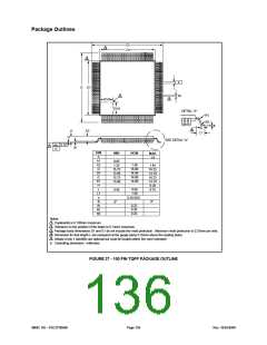
Package Outlines
D
D1
3
3
e
E
E1
W
5
2
D1/4
E1/4
DETAIL "A"
4
R1
R2
0
L
L1
A2
A
H
SEE DETAIL "A"
0.10
1
A1
-C-
DIM
A
NOM
MIN
MAX
1.6
A1
A2
D
0.05
1.35
15.75
13.90
15.75
13.90
1.40
16.00
14.00
16.00
14.00
1.45
16.25
14.10
16.25
14.10
0.20
D1
E
E1
H
L
0.60
1.00
0.50 BSC
0.45
0.75
L1
e
0
8°
0°
W
R1
R2
0.25
0.20
0.20
Notes:
1
2
Coplanarity is 0.100mm maximum.
Tolerance on the position of the leads is 0.13mm maximum.
3
Package body dimensions D1 and E1 do not include the mold protrusion. Maximum mold protrusion is 0.25mm per side.
Dimension for foot length L are measured at the gauge plane 0.25mm above the seating plane.
Details of pin 1 identifier are optional but must be located within the zone indicated.
4
5
6. Controlling dimension: millimeter
FIGURE 27 - 100 PIN TQFP PACKAGE OUTLINE
SMSC DS – FDC37N3869
Page 136
Rev. 10/25/2000

 SMSC [ SMSC CORPORATION ]